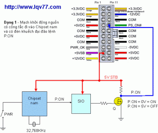
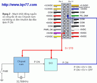
The components of the circuit :
- Power On foot ( green ) of 20pin jack / 24pin ATX power connector on the motherboard .
- STB 5V source ( purple line level before ) .
- STB 3V3 voltage source is from 5V STB ( A14 traumatic Slot PCI)
- Power On Switch 2 pin connector with Power ON the battery panel .
- SiO chip .
- Southbridge , quartz chips 32m for NAM .
- Mosfet island or IC buffer ( if any) .
Circuits are three main forms:


When not strike source ( not press the switch ) :
- Green is the right foot is from 2.5 – > 5V
- 5V source of the STB , there must be 5V purple wire
- Source STB 3V3 ( PCI A14 foot ) should be 3V3 .
- Pin 2 connected to the Power On button on the chassis must have one foot from 2.5v – > 5V .
- SiO and southbridge chips are not hot
When you click the source ( switch button ) :
- = 0V green legs .
- STB 5V 5V source is sufficient
- Sources enough 3V3 3V3
- South Chip little bit warmer .
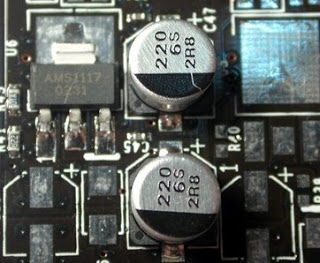
Common Errors : Mainboard Size is not the source .Causes and treatments :Step 1 : Measure the STB 5V purple wire and to have enough . If you drop down to ~ 4.5V or lower is a problem . Unplug the power cord from the main, leaving the measured source size try that if enough 5V jack on Main 4V5 or only the lower circuit is hit . If you touch the test circuit voltage stabilizer circuit prior STB 3V3 ( will have its own article ) , SiO chip , chip Nam , LAN chip , Sound ( if any) . One of the chips from said that they will not touch the source size . If LAN or Sound Chip touch ( touch hand simulation ) , then let go before ( does not affect the operation of main).Step 2 : Check the power supply before 3V3 A14 at the foot of the PCI slot ( found on the 14th column from left – see illustration)

This 3V3 circuit voltage stabilizer voltage stabilizer IC used a 1117 3v3 they or their 1084 , 1085 , 1086 . remains the most common in 1117 . 3 to 5V STB foot , right foot 2 to 3V3 . The main root is not life that used for IC circuit with a few transistors for MOSFET or voltage stabilizer .

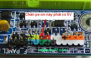
If loss of leg 2 3V3 in the discharge to measure the internal IC and circuit . If the internal position to hold the foot 2 ~ 0 hits 99 % Male chip .Step 3 : Measure the 5V source size ps -on (Maybe a little less than okay ) at the foot of PS -ON (2 pins connected to a vacuum source that switches on a ps – connected foot mass – see picture ) .

If loss of 5V at the foot of the ps -on foot to check on the chip does this go ? South SiO or chip – > open circuit or chip that error .- Detect circuits ( hug scale x1 ) foot chip size and SiO PSON . If resistance hug ~ 0 – > Type 3 : PS -ON size foot management by SiO– If the rest are : PS -ON size foot by NAM management chipsetStep 4 : Check for MOSFET island or not ?– Detect circuits ( hug scale x1 ) Green foot and leg SiO chip . If no resistance hug ~ 0 – > have islands or ic buffer MOSFET– In this format : True green not to be directly over a chip that MOSFET SiO island ( or IC buffer ) . Often this MOSFET ( or buffer IC ) die to not click the source . Find a MOSFET instead of the island is OK . Other cases were short MOSFET Island DS, always in a state machine to ” run ” power on self- run , or complete shutdown continues to ” run ” . < – This case also common.Step 5 : Check that the chip has been hot, NAM ( no size at source )
- If the power supply ( not attack the source ) that chip away NAM roasting hot chip is 100 % dead NAM .
The last step :
- Remaining leg openings NAM chip , chip error or error NAM SiO chip .
- Few cases due to failure of the chip quartz Affairs NAM (instead of trying ) .
- linking together two pi 2 foot quartz was leaked – > always try to let go lightly.
- If SiO chip error : opening leg , then welded or errors, rather well.
- If the chipset South bug : Steam the chips back , do not remove the chip into the foot very close again , is not it rather different chipset .


