Mainboard : Circuits source CPU ( VRM – Regu Vol Module )
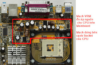
The position of the motherboard VRM circuit
What is VRM ? – VRM is ( Vol Regu Module – Module voltage stabilizer ) – circuit stable voltage for the CPU
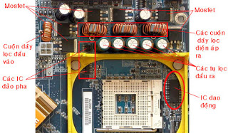
– Circuit VRM ( voltage stability for the CPU ) is usually located next to the CPU socket , circuit components include :
– IC fluctuations ( also called the IC pulse -)
– IC -phase islands ( known as drivers , driving pulse -)
– The lights Mosfet
– The coil ( including the easily recognizable to the coil mounted around the CPU socket – )
– The filter capacitors ( to and around the CPU – )
The function of the circuit VRM a controller for CPU power supply is stable with a relatively large current of about 8 to 10A
You put the mouse cursor on map to view annotation
VRM circuitry on the motherboard ASUS Socket 478
You put the mouse cursor on map to view annotation
VRM circuit on motherboard socket 775 GIGABYTE
VRM circuit on the motherboard GIGABYTE Socket 478
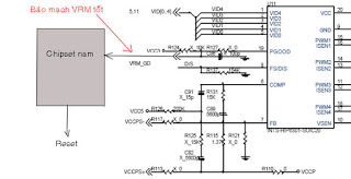
Logic circuit diagram of the motherboard VRM
2.1 – The main component of the VRM circuit
– IC range – function oscillators ( pulse PWM – pulse width modulation ) to control the operation of pairs of light Mosfet
– IC phase Islands – split each range into two opposite -phase oscillation is
– LED Mosfet – Activity -interrupt the control signal of the PWM pulse , the pulse -phase PWM with the Mosfet positive lead , while the negative phase pulse PWM Mosfet is off .
– Coils – combined with capacitors to filter the voltage pulses into DC voltage DC
– Capacitors – combined with the filter coil voltage pulses into DC voltage DC
2.2 – Principles of operation of the VRM circuit :
– When the supply voltage VCC to the IC fluctuations ( ISL 6565A ) simultaneously PGOOD legs ( leg press ATX power problems ) have reported the average voltage ICs will operate , it generates pulses PWM1 , PWM2 and PWM3 to 3 pairs of lights for Mosfet
– The PWM pulse is split into two impulses are in opposite phase when passing through the island IC phase , then the two phases will lead to the opposite impulse control leg of the light G Mosfet .
– When the light pulse is positive Mosfet drivers it would lead , have pulse audio controller it will break , so will shut off lights Mosfet continuous oscillation frequency of the PWM pulse
– Two pairs of lights on each Mosfet will close off alternate lights led the other lights off and vice versa , creating a voltage pulse in the middle .
– After the voltage pulse filter circuit will be L – C filter into a voltage level to one-way flat CPU
2.3 – Features circuit of VRM
– Circuit voltage converter from 12V down to approximately 1.5 V and current up to about 8 from 2A to 10A
– Circuit itself has little capacity loss is only about 20 % effective capacity .
– Denmark has the ability to automatically adjust the CPU voltage level signal through the logic at the foot VID0 , VID1 , VID2 ,
VID3 , VID4 report from the CPU .
– Pentium 4 motherboard on the CPU when not attached to the VID pins and a valued logic circuits give voltage VRM
by default 0V ( note the very important – lqv77)
– Input Voltage VRM on the motherboard ‘s circuitry is 12V 4 pen , 3 pen on the motherboard is 5V
– Voltage output of the circuit on the motherboard VRM 3 pen when not attached to the CPU is about 1.6 V
Logic circuit diagram VRM ( voltage stability for the CPU )
Legend of the IC pins oscillation
– VCC – Power supply for IC
– PWM1 , PWM2 , PWM3 – The foot pulse width modulation to control lead pair of lamps Mosfet
– ISEN1 , ISEN2 , ISEN3 the foot of the current sensor
– EN – Legs for IC operation
– ENLL ( PGOOD foot ) – Foot ATX power status works well
– The foot VID0 , VID1 , VID2 , VID3 , VID4 status logic voltage value for CPU use
– PGOOD , OVP – VRM circuit status of the male chipset
– VSEN – Chan voltage sensor ( foot feedback )
VRM circuit on MSI motherboard
- VRM voltage stabilizer circuit on the motherboard MSI
- The similarities and differences between the motherboard ‘s VRM circuitry Petium Pentium 4 and 3
– Principles of operation of the VRM circuitry on the same two types of motherboard
– fundamental difference between the two types of Main VRM circuit is input voltage of 5V motherboard Pen 3 also use the input voltage of 12V using Mainboard Pen 4
– When not attached to the motherboard CPU VRM circuit the pen 3 is the default voltage 1.6 V VRM circuitry of the motherboard also the default Pen fell down 4 wholesale 0V
- Pentium 3 motherboard has only one pair of lights on circuit Mosfet VRM
- Circuits reported incidents of VRM circuit on male Chipset
– When the VRM circuit will work well for signals of chipset reported male VRM_GD said operating state of the circuit has good stability for the CPU voltage , CPU ready hot action .
– Signal Chipset VRM_GD taken as a condition to give south chipset system reset signal , if VRM circuit does not work or have problems, there will be no signal VRM_GD chipset so that the signal will not reset to boot
VRM circuit test methods – Test for CPU supply
When checking the voltage level for the CPU , you should note the following few points :
– With a Pentium 3 motherboard , you can then check for the CPU vCore voltage without the need to add CPU Socket
– With the Pentium 4 motherboard to measure the voltage supply for the CPU , the CPU into the socket you need to add before then , if no CPU VRM circuit of the Main Pen 4 the voltage 0V by default .
– Before you add the socket to check the CPU voltage, you first need to measure vCore voltage ( without CPU ) to exclude cases with short circuit Mosfet VRM as increasing vCore voltage may damage your CPU.
6.1 – Position measure vCore voltage ( vCore is a source of supply for CPU VRM )
– Please measure vCore voltage ( voltage for CPU ) measured at the beginning of the month with a DC coil , you can measure in both the first coil are , if the alarm clock is about 1.5 V DC VRM circuit was ” OK ” , if the alarm clock voltage of 0 or below 1V VRM DC circuit is broken.
– Please measure vCore voltage ( voltage for CPU ) measured at the beginning of the month with a DC coil , you can measure in both the first coil are , if the alarm clock is about 1.5 V DC VRM circuit was ” OK ” , if the alarm clock voltage of 0 or below 1V VRM DC circuit is broken.
CPU voltage measured at the top level of the positive windings or capacitors 6.3 V
When measuring the voltage level on the motherboard CPU pen to add four new CPU into the socket then the output voltage
measured at the beginning of the output coil ( from 2 to 4 coil outputs are similar in size )
measured at the beginning of the output coil ( from 2 to 4 coil outputs are similar in size )
6.2 – The test procedure and VRM circuitry on the motherboard vCore voltage Pentium 4
Step 1 – Measure the voltage when not attached to the CPU vCore voltage to 0V by wholesalers fell down , if not already installed when vCore voltage CPU VRM has been short circuit is 12V Mosfet above ( D Mosfet has leg match at 12V )
Step 2 – Install the CPU , power supplies , switch , and vCore voltage measured at the foot of the winding
– If the output voltage between 1.5 V VRM circuit is good
– If the output voltage between 1.5 V VRM circuit is good
– If there is no or a low output voltage below 1V VRM circuit is broken
- Explain the steps above then check :Step 1 (Derived and measured without CPU )
– You power the motherboard , the clock in regulation to lift the standard 10V DC vCore voltage measurement at the top of the coil voltage stabilizer circuit of VRM
– Main Fit Test Card to observe the status of the source
– Turn on the switch ( PWR short legs ) to run the main source , the lamp 3.3 V , 5V and 12V light up on the Test Card is a good source and ATX motherboard is not short
– Measure the leg of the coil voltage of 0 V to prone wholesale ( not add due to CPU VRM output voltage circuit default = 0V )
=> If not found add CPU voltage measured at the top of the coil is about 5 to 10V VRM is being short- circuit Mosfet , you should carefully check the lights Mosfet .Step 2 (Turn the source and measure the CPU into the socket was mounted on the Main )
– Install the CPU into the socket on the motherboard ( CPU certainly is good )
– You power the motherboard , the clock in regulation to lift the standard 10V DC vCore voltage measurement at the top of the coil voltage stabilizer circuit of VRM
– Main Fit Test Card to observe the status of the source
– Turn on the switch ( PWR short legs ) to run the main source , the lamp 3.3 V , 5V and 12V light up on the Test Card is a good source and ATX motherboard is not short
– Measure the voltage coil leg up to about 1.5 V ( since when did add CPU = > VRM circuit voltage should produce about 1.5 V or by using the CPU voltage )
=> If the CPU was mounted at the top which shows the coil voltage ( vCore voltage ) is equal to 0V VRM circuit is not activeYou need to be corrected as follows :
– dry vacuum oscillation pulse PWM IC and IC -phase island
– Check if there are any lights Mosfet not be short ?
– Replace IC PWM pulse oscillation
discussion of :
– This article is for you new to the job is extremely difficult not aware ” operating principles ” of the circuit . But for the makers of ” e ” because it is relatively simple circuit ” of the pulse voltage stabilizer “normal . Voltage pulses of this form if you learn via TV or monitor it more complicated . In TV or CRT Monitor circuit ” of the pulse voltage stabilizer ” to get the signal source ” non- recovery ” from ” High voltage transformers ” on … But in this circuit is simply the pulse , there is a supply voltage output . If the CPU would be good ” feedback ” VID0 , VID1 , VID2 , VID3 , VID4 continued operation of vessels , if not better CPU ( or CPU contactless good death ) , the stop pulse level – > interrupt output .
– If you lose power supplies for CPU : check back from the CPU ( make sure the CPU better) good contact with socket CPUs , the best MOSFET ( not touching , breaking , leakage … ) Good Driver IC ( measured by current or wave instead test ) pulse of good IC ( measured by the wave , or rather try ) .
– this circuit if the ” e ” is an easy experience by going to discover information essential http://www.alldatasheet.com to investigate the pulse is on the IC will have an analysis of operating principle details . The English course, then . The more your self-discovery from this suggestion lightly. hardware that people do not know , just as people spend http://www.alldatasheet.com ” removable ” only.
– Because this circuit operation with very high flow should probable damage in this area is great. Know and fix the principle of this circuit is successful 60-70 %
– Early notice important element of this circuit should also have my own an article in the same subject but by receiving and presenting different. All further references .
* Reminder : This article collected from different hocnghe.com but when you see the article at is no registration , login , or waste any cost. In addition you can also download full set of documents for future reference . Furthermore, questions related comments you might meet and get back in the shortest time possible.


