Motherboard Gigabyte GA-8LD533 maintenance log
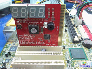
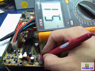
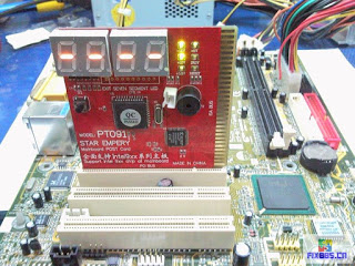
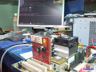
Visual values are no problem playing, plug in the power test card was found on the 3.3VSB standby light does not shine
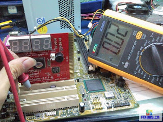
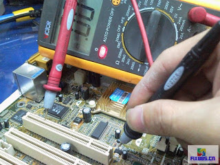
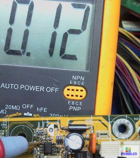
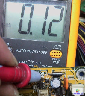
PC114 pin voltage is measured only 0.02V should be 3.3V】 【normal
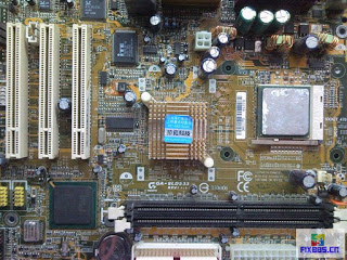
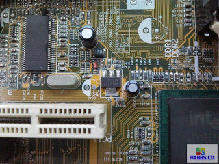
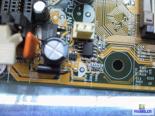
No standby voltage, first of all on-board to find standby voltage generator components, found a 1117 and a 1084
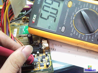
In order to determine that is to generate 3.3VSB voltage components, a table pen then A14, a table pen test to 11173 feet. 11173 feet and the A14 was found attached to illustrate the feet 3.3VSB VCC switch to 1.5V SB VCC voltage components.
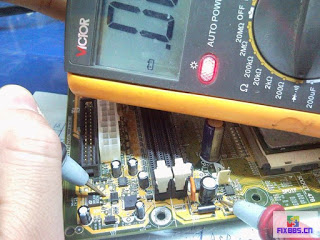
Test-retest 10842 feet and 11173 feet, similarities demonstrate that it is 5V SB over 1084 conversions 3.3V SB, then certainly 3.3V SB come from the 1084 conversion.
Under normal circumstances, the direct access 5VSB pin sub-10843 replaced 3.3V SB, measuring purple 5V SB with 10843 feet was found not directly linked to
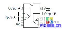
5V SB line was found running with the CPU near Block LM393 comparator 8-pin connected
Cha LM393 data, 8-pin power supply pin, a pin for the way out, way out to 7 feet
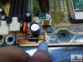
Kick start running line, was found into a 6-foot sesame tube 3 feet, model D1Y13
View Sesame tubes found in 1256 pin-pin connected together, then 10843 feet. 4 feet direct access 5VSB
I do not know what it is 6 feet, help the master craftsman was the sesame tube pin map, found a P pipe ditch
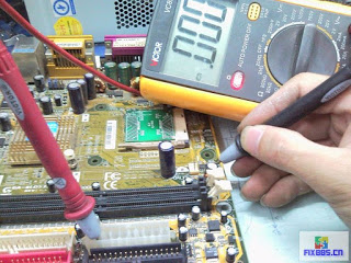
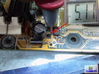
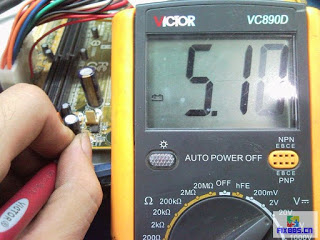
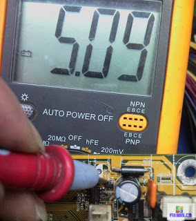
Pin diagram found on the tube voltage electric measuring 4 feet sesame seeds (S) 5V
Test-retest 3-pin (G) voltage is 5V, P-channel MOS control voltage until the output should be 0V. No wonder there is no standby voltage of 10843 feet, the original output of this tube did no
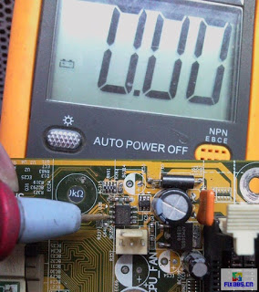
Prior to running lines of this MOS tube is then 393 of the G pole. So check the working conditions of 393. Measuring 393 positive input pin, the voltage of 0V
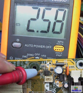
Test-retest reverse input voltage 2.5V
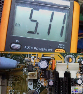
Test-retest output pin 5V, this is obviously and 393 works contrary. Under normal circumstances only the positive input is higher than when the reverse input, the output pin until the output voltage, suspected damage 393.
Replacement of 393 and then measuring the forward voltage input pin, the voltage of 0V
Reverse input voltage remains at 2.5V
Test-retest output pin, and now a voltage of 0V
MOS control voltage for 0V the
MOS pipe D has a normal output of 5V has an extremely
10843 feet finally 5V Voltage
Point switch trigger, smooth boot
U test voltage is normal on the boot memory to run code on the display. Repair faults.


