MB L3 Training Materials ACTRE (ASUS Certificate Training of Repair Engineer)
mb l3 training materials.pdf
Chapter 1. MB Frame Structure……….……P5~P14
Chapter 2. Voltage…………………………P15~P39
Chapter 3. Clock…..…………………………..P40~P51
Chapter 4. Power On Sequence.……..….P52~P60
Chapter 5. PS/2………………………………..P61~P74
Chapter 6. USB…………………………………P75~P87
Chapter 7. Com Port……………………….P88~P100
Chapter 8. Print Port……………………..P101~P121
Chapter 9. FDD……………………………..P122~P131
Chapter 10. IDE……………….……………P132~P142
Chapter 11. SATA…..……………………P143~P153
Chapter 12. RAID………………………….P154~P173
Chapter 13. AGP ………..………………..P174~P193
Chapter 14. Onboard VGA……………..P194~P202
Chapter 15. Audio…………………………P203~P219
Chapter 16. Game Port………………….P220~P231
Chapter 17. PCI…………………………….P232~P254
Chapter 18. PCI-E………………………….P255~P273
Chapter 19. LAN……………………………P274~P298
Chapter 20. 1394………………………….P299~P322
Chapter 21. Memory…..………………..P323~P364
Chapter 22. Battery Circuit……………..P365~P373
Chapter 23. Hardware Monitor ……….P374~P391
Chapter 24. BIOS…………………………..P392~P405
Chapter 25. SMBUS……………………….P406~P424
Chapter 26. POST Code………………….P425~P464
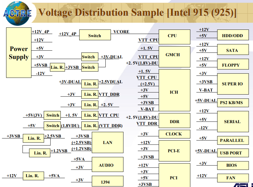
voltage Distribution –Intel 915 (925) series
Voltage Distribution –Intel P4 (Old models)
Voltage Distribution Detail Sample-P4S800D
Linear & Switch Regulator
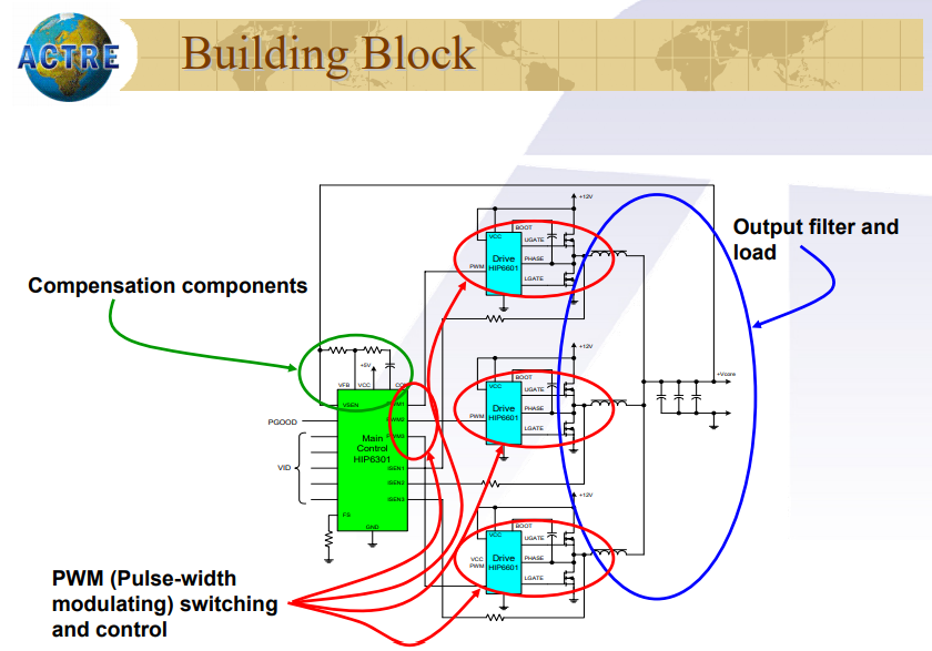
Vcore Multi-Phase Architecture
Vcore Multi-Phase Controller Sample ADP3180
Vcore Problem Debug Procedure
Vcore Problem Debug Procedure (1) Problem Debug Procedure (1)
If no Output
Check if both 5V and 12V are OK
Check POWER MOSFET (both UGATE/ LGATE) are
not short
Check all VIDs of Power Regulator are not high
Check EN/FS of Power Regulator is not zero Volt
Vcore Problem Debug Procedure (2) Problem Debug Procedure (2)
If the output voltage wrong
Check if VIDs of Power Regulator are wrong
setting
Check if the feedback resistor divider is wrong
Check if UGATE and LGATE of Power Regulator
with wrong voltage level
Check if POWER MOSFET failure
General Power On Sequence
Power On Sequence with Reset (General)
Power On Sequence with Reset (W/ASUS ASIC)
Power On Sequence with Reset (P5GD1 Sample)
Power On Sequence with Reset (P4P800 Sample)
No Power Problem Debug Point
No Power Problem Debug Point No Power Problem Debug Point
POWER UP PROBLEM
1. Check if any burned components or traces
2. Check no voltages short with GND such as +5,
+12 , +5VSB, +3, -12, +3VSB, VCORE 1.5V, 2.5V
3. Check Battery voltage
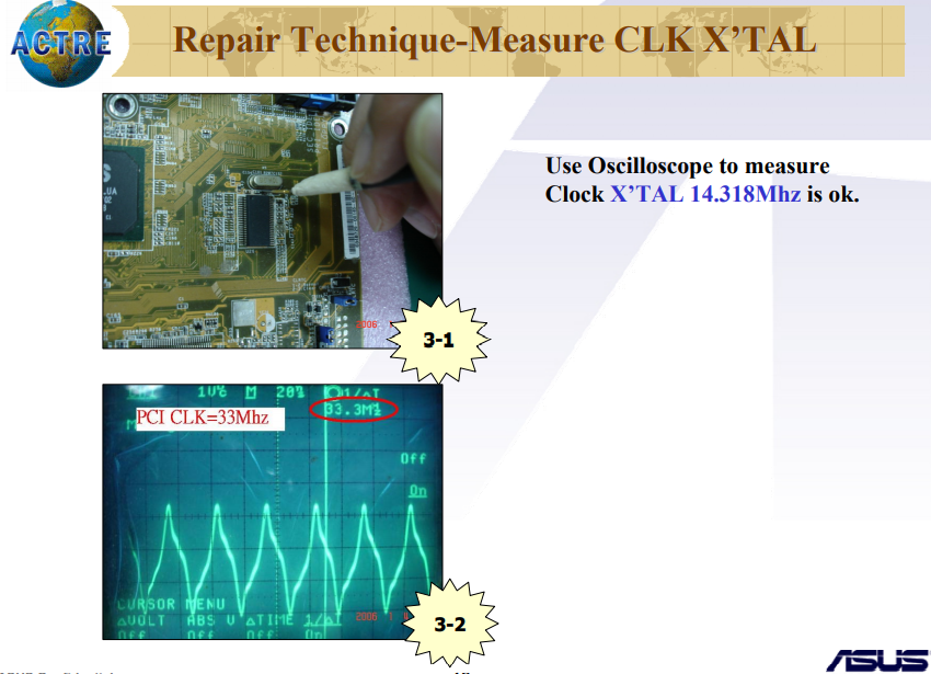
4. Check X’tal 32.768 KHz
5. Check 5VSB ,3VSB, PWRBTN#
6. Check PSON signal & related circuit
[ebook_store ebook_id=”13011″]