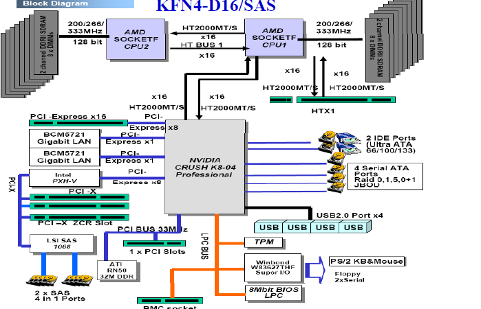
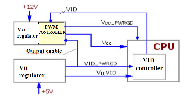
-SERVER MB Frame
Structure
-Nvidia Crush K8-04 Block Diagram
-Nvidia Mcp55 pro Block Diagram
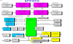 -Nvidia Io55 Block Diagram
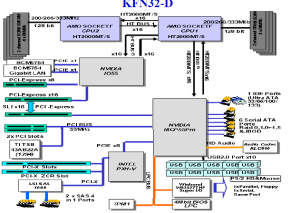
-Intel 5000P Block Diagram
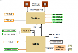
-Intel E7525 Block Diagram
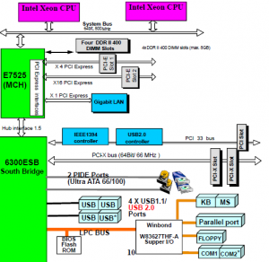
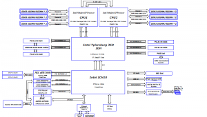
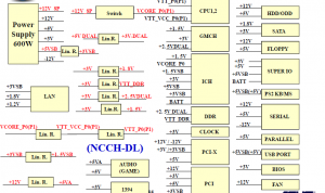
Z8PE-D12X Block Diagram
-Q & A (Repair Experience)
-Power On Sequence
-Power Supply Overview
-Power Supply – PSON#,5VSB
-Power Supply – PSON#,5VSB
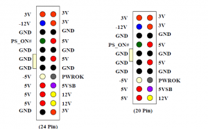
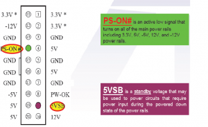
-PSON# :
This is a input signal from ATX POWER. The theorem
of operation is, when the ATX POWER has connected
to the MB(the MB isn’t “ON” yet, but the ATX
POWER is “ON”), that provide 5VSB and
PSON#(ATX POWER wouldn’t provide 5V,12V when
the PSON# is “HIGH”, or that provide 5V,12V when
the PSON# is “LOW”), and then MB will connect the
PSON# a register to the 5VSB ensuring no 5V and
12V current out put to the MB
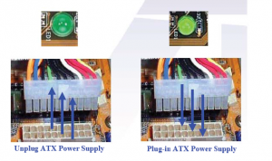
-Power Supply – Standby Voltage
-Advanced Configuration and Power Interface
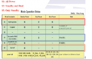
-Advanced Configuration and Power Interface
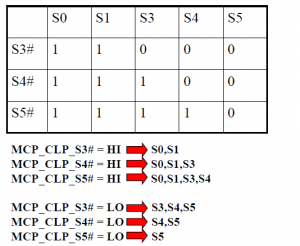
-Power On Sequence
Power On Sequence :The three main steps
1st : none of the power source step , this step have
the Battery and Standby source
1. RTCRST#
2.RSMRST#: When the S.Bridge’s voltage is ok ,the RST
signal that input from I/O touch off the
S.Bridge internal circuit
2st : prepare to supply the power source
1.PWRBTN#
2.IO_PWRBTN#
3.S3#,S4#
4.PSON#
3st :
– Before the “POWER OK” of all main power on MB
Reach to the stable status.
-The Power Sequence is different between Intel and
AMD flat.
-The different chipset has different requirement.
-AMD needs a dedicated chipset to control the
CPU power sequence as following:
1.VDIMM_STR_EN: Memory voltage enabl
2.VDDA_EN: CPU PLL power enabl
3.VCORE_EN: Vcore power enable
4.VLDT_EN: Hyper Transport I/O power
-The power sequence of intel
1.VTT_CPU Vcore enable VRMPWRGD
VRMPWRGDa rest of MB connect to S.Bridge(3v) and CPU Socket(1.2v)
-Power On Sequence sample
KFN5-Q/SAS
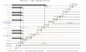
-Power On Sequence sample
KFN5-Q/SAS
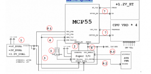
-Power On Sequence sample
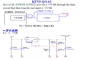
-Power On Sequence sample
When the user click the bottom of PWRBTN#, it make the PWRBTN#
KFN5-Q/SAS
“LOW” and generate +1.5V_DUAL,+3V_DUAL,+5V_DUAL
+3VSB +3V_DUAL +1.2V_DUAL(1.15V)
After +3VSB and +3.3V through the linear circuit and generate a
+3V_DUAL voltage. Then it through an another linear circuit and
transfer a +1.2V_DUAL voltage.

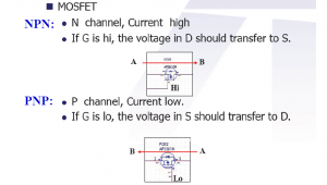
-Power On Sequence sample
Next picture is a +3v_dual circuit, which is having a voltage from +3v or +3vsb.
First, it’s only a BUF_S3# by the standby voltage status, all SIO_PWRGD are
low potential, because the D41(A point) is LOW potential, it’s make PQ104 in
stopping status. At the same time, you can measure a 0.712v voltage ,then make
the PQ103,PQ105 from work area to full status slowly.It also makes the C,D
become low potential state, then PQ101(N-Channel) and PQ102(P-Channel) S-D
gate, present a leads open and the other closes, therefore, it getting a 3V_DUAL
voltage
In standby state, PQ101 S-D closes PQ102 leads open, +3V_DUAL is offered by +3VSB
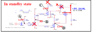
Power On Sequence sample
In power on state, PQ101 S-D leads open PQ102 closes, +3V_DUAL is
offered by +3.3v
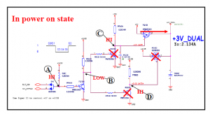
-Power On Sequence sample
KFN5-Q/SAS
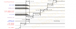
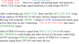
After generate the +3V_DUAL, X2 will have a 25Mhz clock,and
provide 25Mhz clock for south bridge,then SPUER I/O output a
SIO_RSMRST(PWRGD_SB)Signal to south bridge.
When south bridge get to know the PWRBTN
ground shorting,
south Bridge feed back MCP_CLP_S5# to SUPER I/O .
-Power On Sequence sample
KFN5-Q/SAS
-Power On Sequence sample
KFN5-Q/SAS
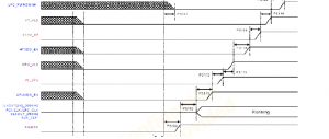
After the south bridge send a CPUVDD_EN signal to CPU VRD circuit.it generate
a +V_CPU(Vcore) , the CPU will resend a PWRGD signal VRMPWRGD to .
MCP55’s CPU_VLD上, +1.2V_HT is the same with the MCP55 , which is sending
HTVDD in +1 2V circuit after the +1 2V HT is generated then feedback a
HTVDD_EN 1.2V_HT circuit,1.2V_generated,HT_VLD (PWRGD) to south bridge.finally,finish whole POOWER Sequence circuit
-Reset introduction
KFN5-Q/SAS
-Reset introduction
Reset introduction
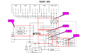
This motherboard most of RESET are out of MCP55,the description will be
interpret as following:
KFN5-Q/SAS
(A):PCI_RST1#:The signal “RESET” is provided by MCP_PCI_RESET#1 to
IDE, this signal is a low voltage action when MCP_PCI_RST1# in LOW voltage,
IDE will be RESET.
Reset introduction
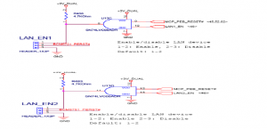
This figure has shown the ENABLE RESET signal which is composed
of U13 AND gate.LAN1_EN,LAN2_EN out of S.bridge MCP55, and
MCP_PEB_RESET# out of MCP_PEB_RESET#_BUF(from S.bridge)
and SIO_PWRGD is generated by a U62’s AND gate.
-Reset introduction
-Reset introduction
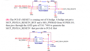
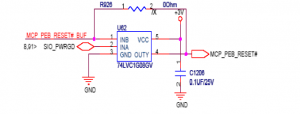
PXH-V’s RESET is coming out of S bridge S bridge out put a
KFN5-Q/SAS
The PXH Vs S.bridge. S.MCP_PEB_RESET#_BUF and a SIO_PWRGD from SUPER I/O,
then pass through the AND gate of U62 7408 to generate the
MCP_PEB_RESET# that provide to PXH-V
Reset introduction
(C):The PCI-X SLOT’s RESET is coming out of S.bridge. S.bridge out
KFN5-Q/SAS
put a MCP_PAPCIRST#_AND and a SIO_PWRGD from SUPER I/O,
then pass through the AND gate of U8 7408 to generate the
PXHV_PAPCIRST# that provide to PCI-X LS1068 SAS RESET is
coming out of PXHV_PAPCIRST# and SAS_EN, then pass through U13
AND to generate the SAS RESET# to provide the LSI1068

Reset introduction
(D):ATI RN50 and PCI SLOT’s RESET is coming out of S.Bridge. The
MCP_PCI_RESET#0_R of S.Bridge which is passing through R9172 to
generate the MCP_PCI_RESET#0
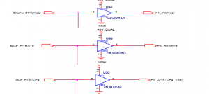
(E): (Sideband Signal Buffer Circuit.) compose of U3 U4 U5
that are all Buffer IC. CPU_RST#,CPU_PWRGD,HT_STOP# CPU
these three signals are sended by S.bridge MCP55 passing through by
Buffer IC directly
No Power Problem Debug Point
POWER UP PROBLEM
1.Check if any burned components or traces
2.Check no voltages short with GND such as
+5v,+12v,+5vsb,+3v,-12v,+3vsb,vcore,+1.5v,+2.5v
3.Check Battery voltage
4.Check X’tal 32.768khz
5.Check 5vsb,3vsb,PWRBTN#
6.Check PSON signal & related circuit
Q & A (Repair Experience)
Battery Circuit
CLRTC setting
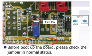
Battery Diagram sample
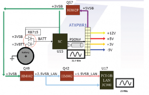
Battery Circuit Diagram
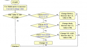
Repair Flow Chart
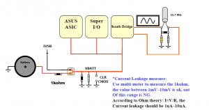
1.Measure Current Leakage
1. Use multi-meter to measure 1k
ohm near the battery circuit, the
value between 1mV~10mV is ok,
out Of this range is NG.
(A di Oh h
According to Ohm theory:
I=V/R, the Current leakage
should be 1uA~10uA.)
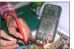
2.Check Battery,Diode…
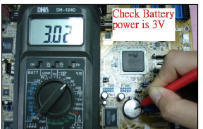
2. If the value is NG, check the
battery voltage is 3V. If not,
change battery and measure the
leakage current again.
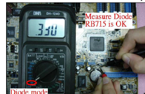
3. If the value is still NG, check
the diode (RB715F) near battery
is ok. If NG, please try to change
it and measure again.
3.Check Vbatt connection
4. If the value is still NG, check
which component use Vbatt. Most
MB Vbatt connect to SB, I/O and
ASUS ASIC. We can strip up the
Vbatt pin of I/O and ASIC to
confirm which component is NG.
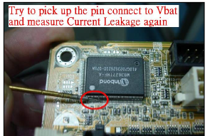
5. If it’s not I/O or ASIC problem
finally please try to change SB.
Q & A (Repair Experience)
-Voltage
Voltage Distribution Sample 1
Voltage Distribution Sample 2
(KFN5-Q\SAS)
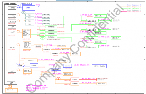
Voltage Distribution Sample 2
(KFN5-Q\SAS)
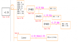
Voltage Distribution Sample 2
(KFN5-Q\SAS)
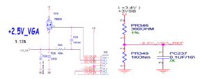
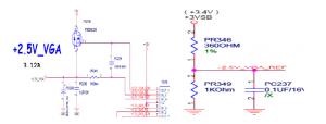
+2.5V_VGA:
Voltage Distribution Sample 2
(KFN5-Q\SAS)
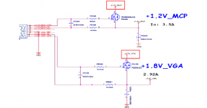
Voltage Distribution Sample 2
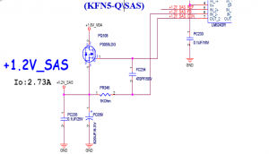
Voltage Distribution Sample 2
(KFN5-Q\SAS)
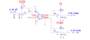
Voltage Distribution Sample 2
(KFN5-Q\SAS)
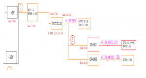
Voltage Distribution Sample 2
(KFN5-Q\SAS)
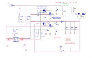
Voltage Distribution Sample 2
(KFN5-Q\SAS)
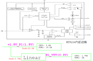
Voltage Distribution Sample 2
(KFN5-Q\SAS)
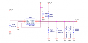
Voltage Distribution Sample 2
(KFN5-Q\SAS)
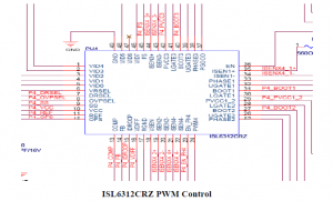
Voltage Distribution Sample 2
(KFN5-Q\SAS)
Vcore
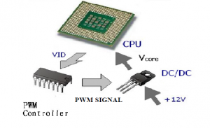
Vcore
Vcore Problem Debug Procedure (1)
If no Output
Check if both 5V and 12V are OK
Check POWER MOSFET (both UGATE/
LGATE) are not short
Check all VIDs of Power Regulator are not
high
Check EN/FS of Power Regulator is not zero
Volt
Vcore Problem Debug Procedure (2)
If the output voltage wrong
Check if VIDs of Power Regulator are wrong
setting
Check if the feedback resistor divider is wrong
Check if UGATE and LGATE of Power
Regulator with wrong voltage level
Check if POWER MOSFET failure
Q & A (Repair Experience)
Clock
CLOCK Generator
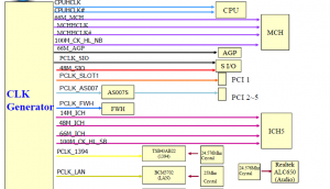
CLOCK Generator Sample-1
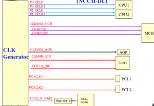
CLOCK Generator Sample-1
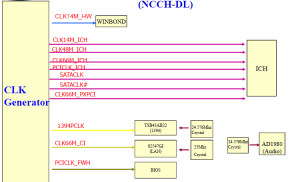
CLOCK Generator Sample 2
(KFN5-Q\SAS)
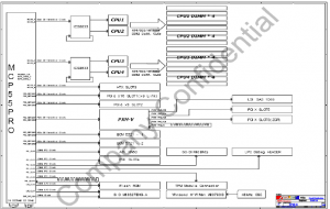
CLOCK Generator Sample 2
(KFN5-Q\SAS)

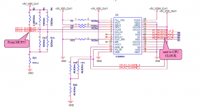
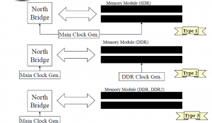
The S.bridge needs a 25Mhz crystal x2 to help the MCP55 that
working internal. The following figure has shown the clock from CPU
to generate the block diagram. the clock from CPU is provided by a
ICS8366. First of all, there is a CPU12_CLKINBUFF_H/L from the
MCP55 to the U1, then out put the CPU’s clock from the U1’s PIN
Q1/NQ1 , Q2/NQ2. The clock of DIMM is provided by CPU. Pls
check the location of +3V_VDD_CLK1,+3V_VDDA_CLK1,U1
PIN1,3 to make sure the voltage value is 3V or not.
CLOCK Generator Sample 2
(KFN5-Q\SAS)
CLOCK Generator Sample 2
(KFN5-Q\SAS)
The other PCI Slot, the clock of the devices are generated by the S.bridge MCP55.
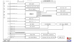
Repair Flow Chart
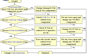
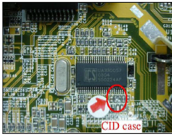
Repair Technique 1.Visual Inspection
Visual Inspection to check
Clock Generator and related
small components are not
damaged.
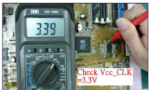
2.Measure Vcc_CLK
Use Multi-Meter or
Oscilloscope to measure
Clock voltage 3.3V is ok.
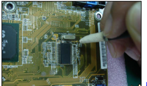
3.Measure CLK X’TAL
Use Oscilloscope to measure
Clock X’TAL 14.318Mhz is
ok.
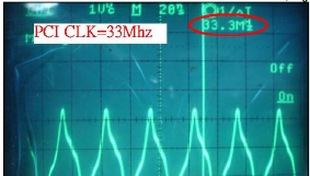
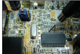
4.Check Individual NG signal
Use Oscilloscope to
measure every individual
CLK signal. If find error
please trace the circuit to
find it’s connection.
d t s co ect o .
If related RLC
components are ok but
CLK still is NG please try
to change CLK generator
at last.
Q & A (Repair Experience)
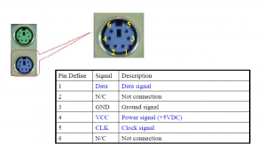
PS/2
PS/2 Diagram
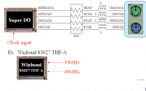
Signal Name (PS/2 Mouse)
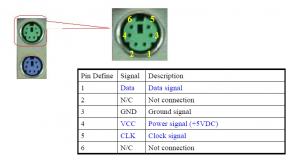
Signal Name (PS/2 KB)
Repair Flow Chart
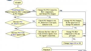
Repair Technique 1.Visual Inspection
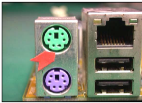
Visual Inspection check PS/2
connector
is no damaged or bent pin.
Check RLC components near PS/2
connector is no damaged.
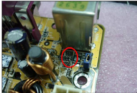
2.Check 5V_Dual
Use Multi-meter to check 5V_Dual
for PS/2 is OK, if NG check
KBPWR Jumper is mounted, then
check Inductor & Fuse are OK,
PCB trace is not open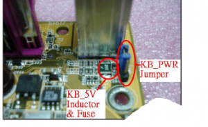
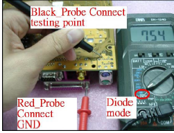
Check K/B CLK, Data & Mouse
CLK, Data. Use multi-meter to
connect GND & check point,
then measure the bias voltage
value. If the value is low please
check capacitor and RLC
component is no short, if the
value is high check inductor.
resistor & trace is no open.
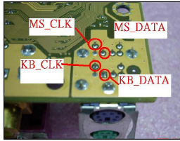
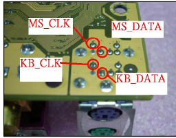
If the problem is still existing
please change Super I/O or
South Bridge at last. Exchange
I/O or SB depends on PS/2 CLK,
96p ,
Data connect to which
component.
Q & A (Repair Experience)
USB
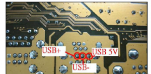
USB Diagram
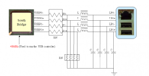
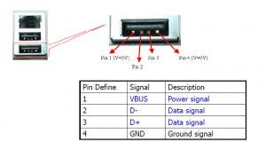
Signal Name
Repair Flow Chart
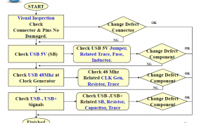
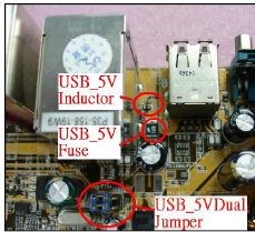
Repair Technique 1.Visual Inspection
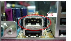
Visual inspection check
USB connector
appearance and inside
pins no damaged, USB
5V(SB) jumper is
S ) ju pe s
mounted.
2.Check USB 5V_Dual
Use Multi-meter to check USB 5V
Vcc (5V_Dual) is correct.
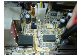
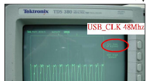
3.Check USB CLK
Check USB CLK 48Mhz from
CLK Generator.
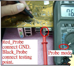
4.Measure USB-,USB+
Use Multi-meter to measure
USB-,
USB+ bias voltage value. The
value should be the same. If you
find the value is high, please
check related resistor or inductor
is ok & trace is not open. If the
value is low please check there’s
no component short or SB short.
If the problem is still existing
after you check above, please try
to change South Bridge.
Q & A (Repair Experience)
Most of USB problems caused by USB 5V
Vbus (Vcc) is not correct. Sometimes we
can find inductor bad, trace burned or forgot
to mount USB jumper.
If You’ve checked USB 5V, 48Mhz, USB-
& USB+ signals but can’t find unusual root
cause, please try to change South Bridge.
COM Port
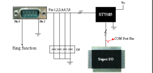
COM1 Diagram
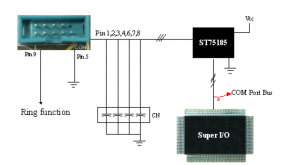
COM2 Diagram
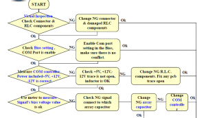
Repair Flow Chart
Q & A (Repair Experience)
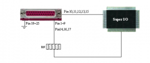
Print Port
Diagram
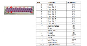
Signal Description
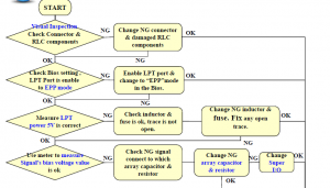
Repair Flow Chart
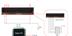
FDD
Diagram
Repair Flow Chart
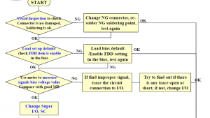
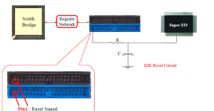
IDE
Diagram
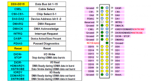
Signal Description
Repair Flow Chart
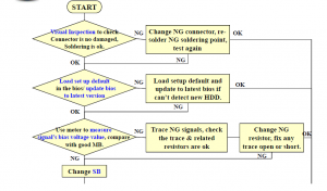
Repair Technique 1.Visual Inspection
Visual Inspection to check
IDE connector is no
damaged, soldering points
are ok.
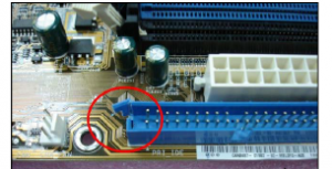
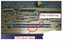
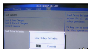
2.Check BIOS
Load Bios setup
default, update to the
latest Bios version
before testing.
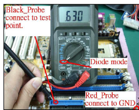
3.Measure IDE Signals
Use multi-meter to measure
signal’s bias voltage value.
Compare with good MB.
If the value is high please
check related trace is not
open, related resistor is ok &
SB is not poor soldering.3 If the value is low check the
trace is not short, the resistor
is ok & SB is not short.
If above way is not the real
root cause please try to
change SB.
-SATA
-Diagram 1
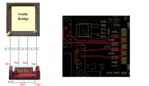
-Diagram 2
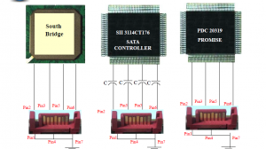
Signal Description
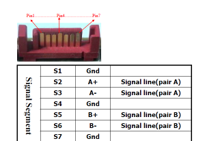
Repair Flow Chart 1
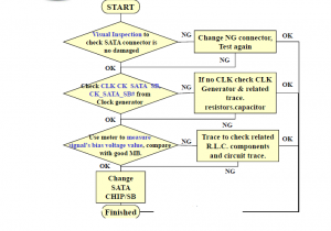
Repair Technique 1.Visual Inspection
Visual Inspection to check
SATA is not
connector damaged.
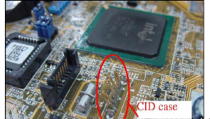
Measure sata 1.8v and
3V is correct
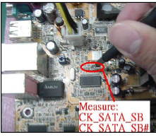
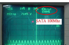
2.Measure SATA CLK
Measure from
SATA CLK CLK Generator or
20M,33M from X’tal
3.Measure SATA Signals
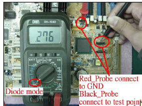
Use Multi-meter to measure
SATA signals (A+ &A- , B+ & B-)
Trace the circuit to SATA chip or
SB if any signal is error. If there
is no trace short or open please
try to change SATA Chip or SB.
-RAID
Raid Diagram
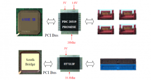
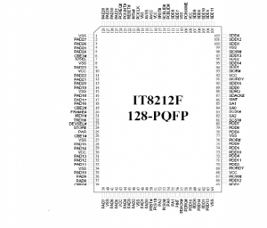
ITE 8212F Diagram
Repair Flow Chart
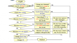
Repair Technique 1.Visual Inspection
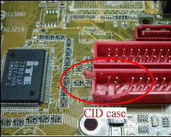
Visual Inspection to check
jump
Raid connector, chip,and related trace,
component is not damaged.
2.Check BIOS Setting
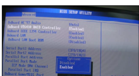
Check Raid setting is enable
i th Bi
in the Bios.
3.Measure Raid Voltage
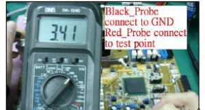
Use Multi-Meter to measure
Raid voltage.
4.Measure Raid Clock
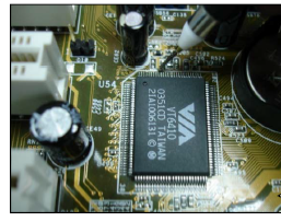
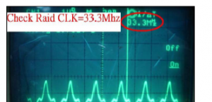
Use Oscilloscope to
measure Raid clock (20M
or 33.3Mhz).
5.Measure Other Signals
Use Multi-Meter to measure
Raid AD signals bias voltage
value.
Due to Raid AD signals are
connect to “PCI” AD signals
PCI signals,
we can also use PCI signal
measure card to measure AD
signals will be easier (Fig. 3-2).
If still cannot find any
abnormal please try to
change Raid controller and
check other under
device PCI bus.
If the problem is still existing
151
5-p g
after change Raid controller
please change SB at last.
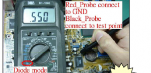
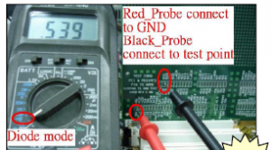
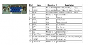
-On Board VGA
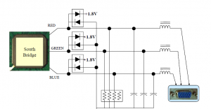
On Board VGA Diagram 1
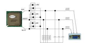
On Board VGA Diagram 2
Signal Description
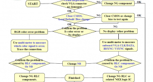
Repair Flow Chart 1
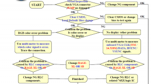
Repair Flow Chart 2
Repair Technique 1.Visual Inspection
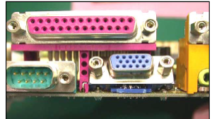
Visual Inspection to check
VGA connector is no pin
bent, the connector is no
damaged.
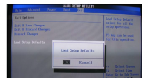
2.Load Default / Check BIOS
If onboard VGA is no display,
please clear CMOS, load Bios
default at first. If no use, please
try to change Bios.
3.Measure VGA Signals 1
Check the problem belongs to (i) RGB
color error problem (ii) No display
or display error problem.
(i)RGB color error problem please use
multi-meter to measure which color (R.G
.B.) signal is error. Trace the connection
to confirm related inductor or capacitor
is ok. If it’s not caused by R.L.Q. small
s o . s o c used . .C.s
components please change NB.
(ii)No display or display error (not
included color error). Use the meter to
measure bias voltage value on VGA CLK
& DATA , VSYNC & HSYNC. Trace
the connection to confirm related R.C.
L.Q. and 74xx logic IC is ok. If all check
Q g
items are no problem please change NB.
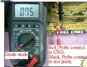
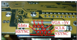
Measure VGA Signals 2
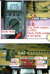
Check the problem belongs to (i) RGB
color error problem (ii) No display
or display error problem.
(i)RGB color error problem please use
multi-meter to measure which color (R.G
.B.) signal is error. Trace the connection
to confirm related inductor or capacitor
is ok it’s R L C Q 3-1 ok. If it s not caused by R.L.C.Q. small
components please change RAGE-XL
OR SB
(ii)No display or display error (not included
color error). Use the meter to measure bias
voltage value on VGA CLK & DATA ,
VSYNC & HSYNC. Trace the connection
to confirm related R.C.L.Q. and 74xx logic
IC is ok. If all check items are no problem
please change RAGE-XL OR SB
PCI
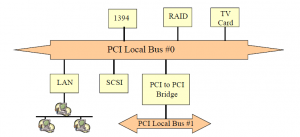
PCI System Block Diagram
PCI Diagram
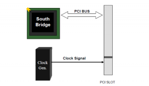
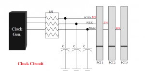
PCI Diagram
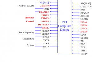
Signal Description
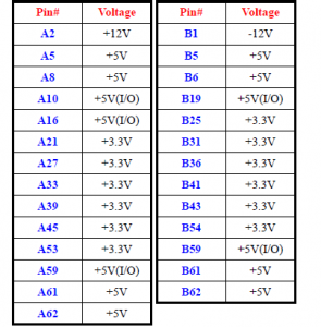
Voltage and Clock
1.Check Voltage: 2.Check Clock:
A mean “Left”, B mean “Right”
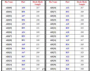
AD Signal
Control Signal
3.Check Control Signal:
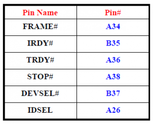
A mean “Left”, B mean “Right”
Repair Flow Chart
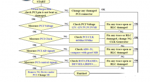
Repair Technique 1.Visual Inspection
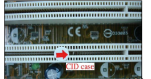
Visual Inspection to check the
PCI connector is no pin bent
or broken.
2.Measure PCI Voltage
Use Multi-Meter to measure PCI related voltages (+12V, -12V,5V,3.3V)
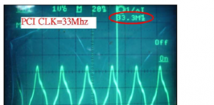
3.Measure PCI Clock
Use Oscilloscope to measure
PCI Clock =66Mhz/33Mhz
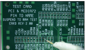
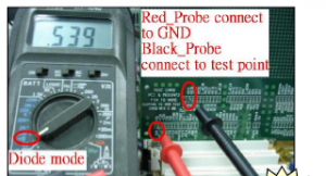
4.Measure PCI Other Signals
Use Multi-Meter to measure
other PCI signals:
AD0~AD31(refer to P16)&
control signals ( FRAME#,
IRDY#, TRDY#……
Compare with good MB. If find
error trace the connection to
find any open trace or short. If
cannot find the root cause
please try to remove other
component under PCI bus and
change PCI controller-SB.
PCI-X
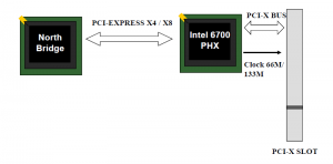
PCI-X Diagram-1
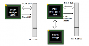
PCI –X Diagram-2
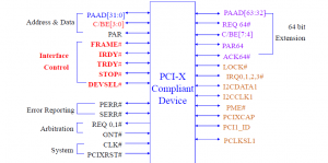
Signal Description
Repair Flow Chart
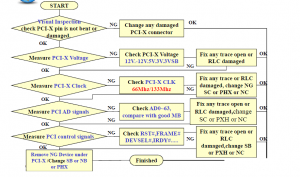
Repair Technique 1.Visual Inspection
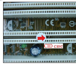
Visual Inspection to check the
PCI-X connector is no pin
bent or broken.
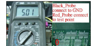
2.Measure PCI-X Voltage
Use Multi-Meter to
measure PCI-X
PCI related
voltages (+12V, –
12V,5V,3.3V)
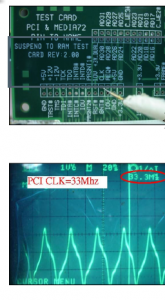
3.Measure PCI-X Clock
Use Oscilloscope to measure
PCI-X Clock
=66Mhz/133Mhz
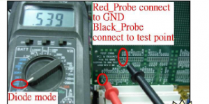
4.Measure PCI-X Other Signals
Use Multi-Meter to measure
other PCI signals:
AD0~AD63 & control signals
( FRAME#, IRDY#, TRDY#…….
Compare with good MB. If find
error trace the connection to
find any trace open or short. If
cannot find the root cause
please try to remove other
component under PCI-X bus
and change PCI controller-SB /
NB /PHX-V
PCI-E
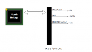
PCI-E X16 Diagram-1
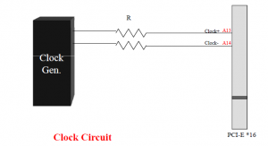
PCI-E X16 Diagram-2
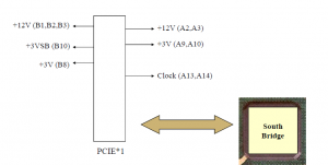
PCI-E X1 Diagram
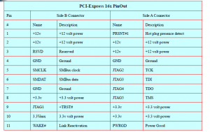
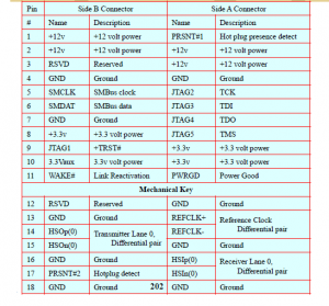
PCI-E X16 Pin Out & Description-1
PCI-E X16 Pin Out & Description-2
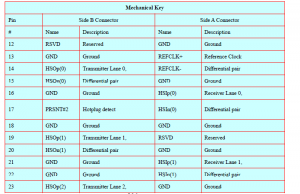
PCI-E X16 Pin Out & Description-3
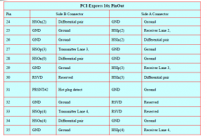
PCI-E X16 Pin Out & Description-4
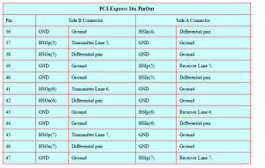
PCI-E X16 Pin Out & Description-5
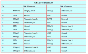
PCI-E X16 Pin Out & Description-6
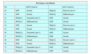
PCI-E X16 Pin Out & Description-7
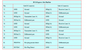
PCI-E X1 Pin Out & Description
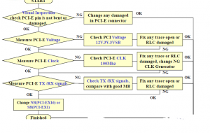
Repair Flow Chart
Repair Technique 1.Visual Inspection
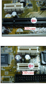
Visual Inspection to check
PCI-E connector is not
damaged or bent pin inside.
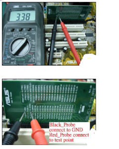
2.Measure PCI-E Voltage
Use Multi-Meter to measure
PCI-E working Voltages—
12V, 3V, 3VSB.
P.S. We can use PCI-E X16
Signals Pin Out card to
measure.
P/N: 08-900036900
Name: ENG_PCI-E PIN
NAME R1 00
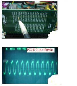
3.Measure PCI-E Clock
Use Oscilloscope to
PCI E CLK
measure PCI-=100Mhz
4.Measure PCI-E TX/RX Signals
Use Multi-Meter to measure
PCI-E TX/RX signals,
compare with good MB.
If find error please trace the
circuit to check related
trace & RLC components.
If still can’t find any
abnormal please try to
change NB (PCI-E X16
controller) or SB (PCI-E X1
controller).
LAN
Diagram 1
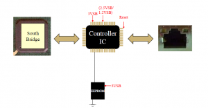
Diagram 2
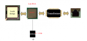
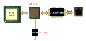
Diagram 3
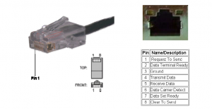
Lan Head Signal Description
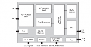
Lan Chip Structure Diagram
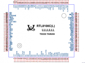
Sample – Realtek 8100C Pin
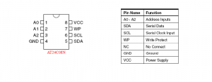
EEPROM Pinout
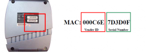
What is MAC Address?
Each device connected to a standard LAN needs a Data Link Layer
address (or called hardware address), providing a means of unique
identification.
Each NIC has its unique, hard-coded MAC (Media Access Control)
address. It is a 48 bits (6 bytes) address written in a hexadecimal format.
The first 3 bytes represents for vendor ID and the remaining 3 bytes are
serial number.
What is IP Address?
Internet Protocol Address
IP address = Network and Host ID Number
– An IP address is a unique software, logical address
assigned to each machine on an IP network.
– It was designed to allow a host on one network to
communicate with a host on a different network,
regardless of the type of LANs the hosts are
participating in.
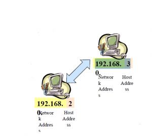
Two major categories of IP address type : 192.168. 3
– Static (Fixed) IP and Dynamic IP
– Real IP and Private IP
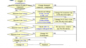
Repair Flow Chart
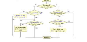
Repair Flow Chart (Lan Mac ID err )
Repair Technique 1.Visual Inspection
Visual Inspection to check Lan
connector & related
components are not damaged
or burned.
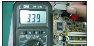
2.Measure Lan Voltage
Measure Lan working voltage
3VSB, 2.5VSB,1.2VSB…1.8V
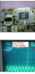
3.Measure Lan Clock
Use Oscilloscope to check
Lan X’TAL 25Mhz &
33.3Mhz (synchronization
with PCI) are ok.
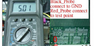
4.Measure AD Signals
Use Multi-Meter to measure
Lan AD signals bias voltage
value.
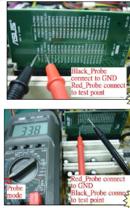
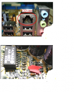
Due to Lan AD signals are
connect to “PCI” AD signals,
we can also use PCI signal
measure card to measure AD
signals will be easier (Fig. 4).
If still cannot find any
abnormal please try to
check other device under
PCI bus.
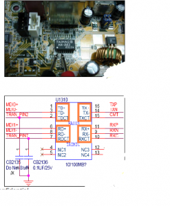
5.Measure Transformer Signals
Use Multi-Meter to measure
Transformer signals. Some
signals should be connected
together (Show as Fig.5-2, the
signals marked orange color)
If Transformer NG, please
change it .
If the problem is still existing
please change Lan controller
first.
If change Lan controller is NG
please change SB at last.
-IEEE 1394
IEEE 1394 Diagram
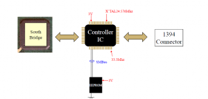
IEEE1394 Introduction
A very fast external bus standard that supports data
transfer rates of up to 400Mbps (in 1394a) and 800Mbps
(in 1394b).
also called FireWire (Apple), iLink (Sony)
A single 1394 port can be used to connect up 63 external
devices.
supports isochronous data — delivering data at a
guaranteed rate. This makes it ideal for devices that need
to transfer high levels of data in real-time, such as video
devices.
What devices are using 1394 interface?
digital cameras, camcorders, printers, TVs, network cards and
mass devices
storage devices.
-Comparison Table
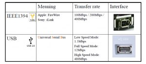
1394a
It’s called FireWire in 1986 (by Apple computer)
It’s called I.Link in 1995 (by Sony)
Features: (IEEE 1394a)
Scalable Performance (S100,S200,S400,etc.)
– S100=100Mbps; S200=200Mbps; S400=400Mbps
Hot Plug
Plug & Play
Support for 63 Devices
Peer-to-Peer Transfer
Maximum Cable Length: 4.5m
1394a Connector
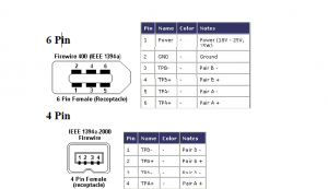
1394b
Features: (IEEE 1394b)
Compatible with IEEE 1394a
Scalable Performance
– 800Mbps
– 1.6Gbps
Add a plug for 9 pin
Cables Defined
– 9 pin to 9 pin
– 9 pin to 6 pin
– 9 pin to 4 pin
Cable material
– POF (Plastic Optic Fiber)
– GOF (Glass Optical Fiber)
Scalable Cable Length
– 4.5m
– 50m
– 100m
1394b Connector
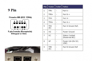
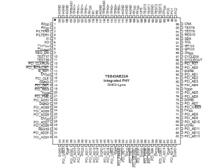
1394 chip –TSB43AB22A Diagram
Repair Flow Chart
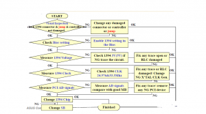
Repair Technique 1.Visual Inspection
Visual Inspection to check 1394
connector, controller & related
small component is not damaged.
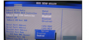
2.Check BIOS Setting
Check 1394 setting is
enable in the Bios.
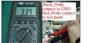
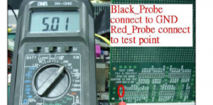
3.Measure 1394 Voltage
Use Multi-Meter to measure
1394 working voltage 3V,5V
(depends on different chip)
4.Measure 1394 Clock
Use Oscilloscope to check
1394 X’TAL 24.576Mhz &
33.3Mhz (synchronization
PCI) are ok
with ok.
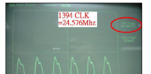
5.Measure AD Signals
Use Multi-Meter to measure
1394 AD signals bias voltage
value.
Due to 1394 AD signals are
connect to “PCI” AD signals,
we can also use PCI signal
measure card to measure AD
signals will be easier (Fig. 5).
If still cannot find any
abnormal please try to change
1394 controller and check
other device under PCI bus.
If the problem is still existing
after change controller
1394 controller,
please change SB at last.
-Memory
Introduction
What is memory anyway?
All computer functions have common features
Data processing (CPU, GPU….)
Data storage (CDR, HDD, Memory…)
Data movement (FSB, PCI-E, USB….)
Control (North Bridge, South Bridge…)
Why memory improve performance?
CPU runs much more faster than HDD.
If all data & application were stored in HDD.
CPU will always wait for HDD to pass data.
Bottle neck in HDD, CPU idle most of the time
Memory CPU.
enhance the usage
-Introduction
Static RAM(SRAM)
Faster, more expensive Need not to be
recharged regularly like DRAM Cache
Dynamic RAM(DRAM)
Less expensive, need to be refreshed
DRAM subtypes to be introduced
Syrchronous DRAM(SDRAM)
Double Data Rate Synchronous DRAM(DDR)
Double Data Rate 2 Synchronous
DRAM(DDR2) Rambus DRAM(RDRAM)
Introduction
Introduction
DDR
Short for Double Data Rate-Synchronous
DRAM, a type of SDRAM that supports data
transfers on both edges of each clock cycle (the
rising and falling edges), effectively doubling
the memory chip’s data throughput.
DDR-SDRAM also consumes less power, which
makes it well-suited to notebook computers.
DDR-SDRAM is also called SDRAM IIand
DDRAM.
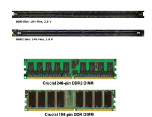
DDR2
DDR2 DIMM memory modules are not backwardcompatible
with DDR DIMM , due to incompatible pin
configurations, core voltage, and memory chip technology.
DDR2 modules are designed with a different “key“ in the
edge connector to prevent insertion into incompatible
memory sockets such as DDR motherboard. A DDR2
SDRAM DIMM will not fit into a standard SDRAM
DIMM socket a DDR DIMM socket.
DDR2 modules use a 1.8V power supply, providing a big
power saving over the 2.5V DDR modules.
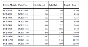
DDR2
DDR2 SDRAM is normally packaged in DIMM modules.
DDR3
DDR3 SDRAM(Double Data Rate Three
Synchronous Dynamic Random Access Memory)
DDR3 SDRAM improves on DDR2 SDRAM in
several significant ways:
Higher bandwidth due to increased clock rate
Reduced power consumption due to 90nm fabrication technology
Pre-fetch buffer is doubled to 8 bits to further increase
performance
The voltage of DDR3 SDRAM DIMM’s was lowered from 1.8V to
1.5V. This reduces power consumption and heat generation, as
well as enabling more dense memory configurations for higher
capacities.
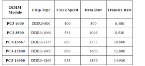
DDR3
DDR3 SDRAM is normally packaged in DIMM
modules. DIMM Module Chip Type Clock Speed
Data Rate Transfer Rate
RAM’s Terminology
ECC
DIMM
Unbuffered DIMM
Registered DIMM
SPD
ECC
ECC (Error Checking and Correcting) allows data
that is being read or transmitted to be checked for
errors and, when necessary, corrected .
It differs from parity-checking in that errors are
not only detected but also corrected. ECC is
increasingly being designed into data storage and
transmission hardware as data rates increase.At
the 64-bit level, ECC requires 8 extra bits.In
general, ECC increases the reliability and security
of any computing or telecommunications system
without adding much cost.
ECC(Cont.)
Unlike parity memory, which uses a single bit to provide
protection to eight bits.
Additional code is needed for ECC protection, and the
firmware that generates and checks the ECC can be in
the motherboard itself or built into the motherboard
chipsets.
It requires more overhead than parity memory for storing
data and causes around a 3% performance loss in the
memory sub-system.

DIMM
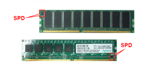
Unbuffered DIMM :
Contains 16 SDRAM chips below
(if ECC (Error Check and Correction) supported, 18 chips)
All the control signals from chipset are directly connected to
corresponding pins of SDRAM chips, without any buffering.
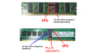
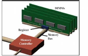
Registered DIMM :
Contains more than 16/18 SDRAM chips, such as 32/36 chips.
For load-driving capacity consideration, all the control signals
need to be driven by 2 registers. And the clock signals from
chipset-memory-controller, need to be re-generated again by a
PLL(Phase Lock Loop) IC.
Unbuffered DIMM
Registered DIMM
Registered DIMM(Cont.)
These registers isolate the module’s heavily loaded
address and control buses from the rest of the system;
thus the system sees only the loading of the registers
on each module instead of the loads from the multiple
memory devices on each module.
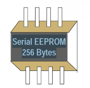
SPD
SPD (Serial Presence
Detection) :
– EEPROM.
– Store certain information of
DIMM module .
Motherboard north-bridge
Serial EEPROM
256 Bytes
chipset will read the content of
SPD via the System
Management Bus, i.e. SM bus
(I2C Bus), and set proper timing
for DIMM module.
SPD(Cont.)
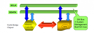
• The SPD device is an 8-pin serial EEPROM chip that stores information
on the DIMM modules’ size, speed, voltage, drive strength, and number of
row and column addresses. When the BIOS reads these parameters during
POST automatically values in the BIOS Chipsetthe routine, it adjusts section for maximum reliability and performance.
Repair Flow Chart
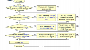
Repair Technique 1.Visual Inspection
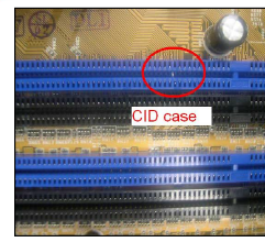
Visual Inspection to check
memory slot is not damaged or
bent pin inside.
2.Measure Memory Voltage
Use Multi-Meter or
Oscilloscope to measure
Memory Voltage.
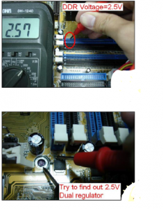
Memory Voltage:
SDRAM: 3V Dual
DDR :2.5V Dual, 1.2Vtt_DDR
DDR2: 1.8 Dual, 0.8Vtt_DDR
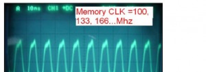
3.Measure Memory Clock
Use Oscilloscope to measure
Memory Clock (100Mhz or
133Mhz, 166Mhz…depends
on different chipset &
memory)
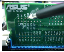
4.Measure Memory Signals
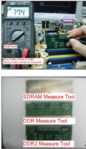
Plug Memory measure card into
slot. Use Multi-Meter to measure
memory signals’ bias voltage
value. Compare with good MB if
you find any unusual.
1. ENG_RIMM R1.00 (SDRAM)
P/N: 08-900019700
2 ENG DDR TEST
2. ENG-DDR-DIMM184 (DDR)
P/N: 08-900019900
3. ENG_DDR2 PIN NAME1.01(DDR2)269
P/N: 08-900037800
Repair Technique
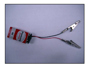
Special Hint when we measure DDR signals*
When we use DDR measure tool to
DDR measure
measure DDR signals, need to add
an extra voltage. We can use one
9V battery across each probe (Red
connect +, Black connect–). The
reason is there are pull high array
resistors between North Bridge &
DDR slot. If without extra voltage
is not able to measure the signals
from slot to NB.
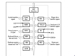
-Hardware Monitor
Diagram
Clock Diagram (for super I/O)
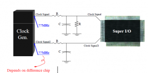
Theorem (Temp. Sense)
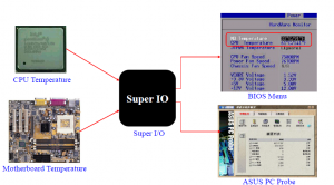
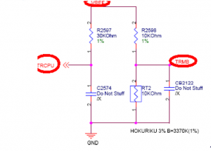
Diagram Sample ( Temp. Sense)
Repair Flow Chart (Temp. Sense)
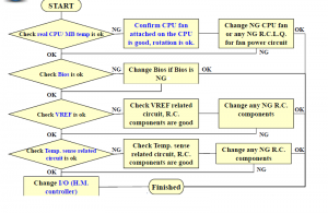
Repair Technique (Temp. Sense)
1. Check real CPU or MB temperature is ok or not,
if ok change bios first; if NG check CPU fan rotation and
contact is good.
2. Check VREF (Reference Voltage). If NG check VREF
related resistor & capacitor(104P).
3. Check Temp. Sense signal (TR CPU or TR MB).
If NG check related resistor & capacitor.
4. If check above signals there’s nothing abnormal, please try
to change super I/O (Hardware Monitor controller).
Theorem (Fan Sense)
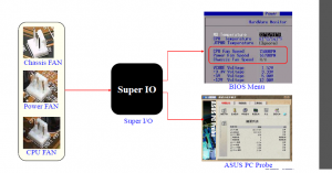
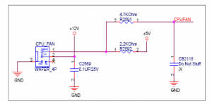
Diagram Sample (Fan Sense)
Repair Flow Chart (Fan Sense)
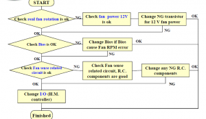
Repair Technique (Fan Sense)
1. Check real fan rotation is ok or not, if NG check fan 12V
related circuit. Especially check fan transistor which
provides fan 12V.
2. Check Bios is ok or not.
3. Check Fan Sense signal (CPU Fan, Chassis Fan, Power Fan).
If NG check related resistor & capacitor.
4. If check above signals there’s nothing abnormal, please try
to change super I/O (Hardware Monitor controller).
Theorem (Voltage Sense)
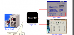
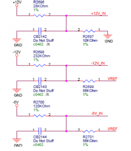
Diagram Sample (Voltage Sense)
Repair Flow Chart (Voltage Sense)
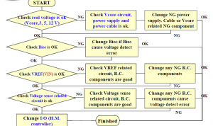
Repair Technique (Voltage Sense)
1. Check real voltage (Vcore, 3.3V, 5V ,12V …..)is ok or not,
if ok change bios first; if NG check Vcore related circuit or
check power supply (power supply cable also included) is
good.
2. Check VIN OR VREF (Reference Voltage). If NG check
VREF(VIN) related resistor & capacitor(104P).
3. Check Voltage Sense signal (12Vin, 5Vin, 3Vin..).
If NG check related resistor & capacitor.
4. If check above signals there’s nothing abnormal, please try to
change super I/O (Hardware Monitor controller).
-BIOS
Diagram
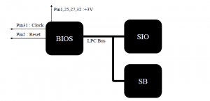
Bios Pin Definition (Intel Sample)
Repair Flow Chart
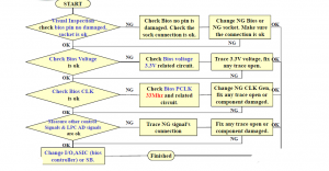
Repair Technique 1.Visual Inspection
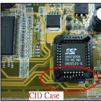
Visual Inspection to check
Bios & the socket is not
damaged.
2.Measure Voltage
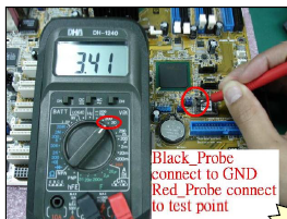
Use Multi-Meter to measure
Bios (PLCC) Voltage 3.3V .
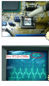
3.Measure BIOS PCLK
Use Oscilloscope to
measure Bios PCLK
(33Mhz)P.S. Not every model pin31
3 connect to PCLK, other
models use for FWE#.
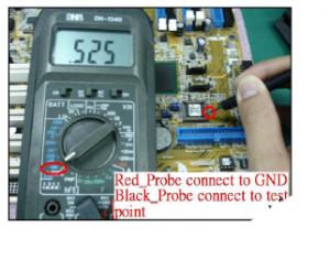
4.Measure Other BIOS Signals
Use Multi-Meter to measure
other Bios signals( DQ.A…)
compare with good MB.
If find error trace the
connection to I/O (BiosController), ASUS ASIC or
SB. Try to change NG
component.
SMBUS
SMbus Strcture
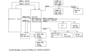
SMbus Strcture
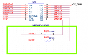
SMbus Strcture
On the last figure, The 74HC4052MX is a Dual 4-
channel analog decoder. The S0 means the SMBS1 and
the S1 means the SMBS2. The “E” signal is the grunding.
On the next figure ,we know that the “E” must be the
“LOW” , then the decoder is ready to work.
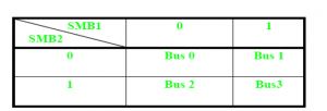
SMbus Structure
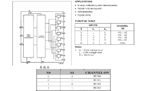
Signal Description
System Management Bus
Connect between IC (Integrated Circuit) chips
Multiple chips can be connected to the
same bus and each one can act as
a master by initiating a data transfer
Two Wires communication
Data line
Clock line
![]()
Repair Flow Chart
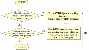
Repair Technique 1.Visual Inspection
Visual Inspection to check
connector, jumper , R.L.C.Q,
Terminator are ok.
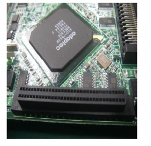
2.Measure SCSI CLK
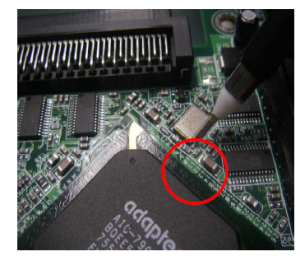
Use oscilloscope to check
CLK 80Mhz is correct, if
NG trace the circuit to
CLK .
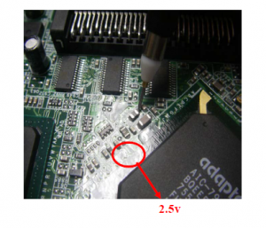
3.Measure SCSI Voltage
Use Multi-Meter to measure
SCSI Voltages—2.5V, 3V,
1.8V.
is ok , If NG check related
component is ok & trace is
not open
4.Measure Terminator’s signals
Use multi-meter to measure
terminator signal’s bias
voltage value. Compare with
good MB.
terminator If the value is high please
check related trace is not
open, related component is ok
& scsi controller is not poor
soldering.
If the value is low check the
trace is not short, related
component is ok & scsi
controller is not short.
If above way is not the real
root cause please try to
change terminator/scsi
controller
-FAN
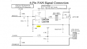
4-Pin FAN Signal Connection
3-Pin FAN Signal Connection
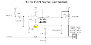
The different from four and three pin FAN is that the 4 pin FAN
has the PWN signal to control the rotational speed of FAN. We set
up the FM_CPU’S jumper in 1-2 short to support the three PIN in
DC mode or set 2-3 short up for four pin FAN in 12V PWN mode.
The voltage is adjusted by the current in the DC mode. The PWM
is the control power to adjust the pulse wide, and we use the
25Khz signal to control the MOSFET that generate the voltage.
The different from DC MODE and PWN MODE is that the
PWN’s efficiency higher than DC MODE . It ensures the FAN’s
voltage Lower than 6V without noise to make sure the reliability.
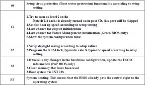
– POST Code
What is POST Code
Using POST Code to Debug
Appendix:
(1) Award Bios Code Definition
(2) AMI Bios Code Definition
(3) Phoenix Bios Code Definition
What is POST Code
POST : Power On Self Test
The tag thrown out by BIOS
– Usually, BIOS would output some number through
80ports. Using I/O access card (debug card), user
could read those number.
– The POST codes used by Award, Phoenix, and AMI
are different.
– These numbers mean something was executing inthe system.
What is POST Code
POST Code as BIOS executing process
Standard POST Code
– These numbers were used as standard process.
BIOS Debug Code
– These numbers depend on various project.
POST “00”, “FF”
POST Code “00”,”FF” or Debug card shows all dots(……) / all 00
(1)Check Voltage:
a)V_core,if no V_core check from power block circuit diagram
b)1.5v,if no 1.5v check from power block circuit diagram
c)2.5v,if no 2.5v check from power block circuit diagram
d)3.3v,if no 3.3v check from power block circuit diagram
e)check for N/B,S/B voltage is ok or not
(2)Check CLK:
a)CPU CLK,if no CPU CLK check from CLK gen. circuit diagram
b)N/B CLK,if no N/B CLK check from CLK gen. circuit diagram
c)S/B CLK,if no S/B CLK check from CLK gen. circuit diagram
d)14.318MHz,if no 14.318MHz check from CLK gen. circuit diagram
e)CLK generator.if all no CLK,change 14.318MHz,and then change
CLK gen. Before must check any open or short
(3)Check Power ok & Reset
a)H/W reset, if low voltage check circuit diagram, normal is capacitor bad
b)power supply power ok, if low voltage, normal is capacitor bad
c)CPU power ok, if low voltage check circuit diagram, and above signal
d)PCI reset, if low voltage check above signal and for S/B CLK, voltage
e)CPU reset, if low voltage check above signal and for N/B CLK, voltage
f)Check boot up sequence.
(4)Check control signal:
a)Check CPU control signal(ADS#,BRDY#…) is ok or not
b)Check PCI control signal(FRAME#,IRDY#,TRDY#…) is ok or not
c)Check others control signal is ok or not
(5)Check Jumper setting:
a)Check USB jumper setting is ok or not
b)Check JEN jumper setting is ok or not
C)Check all jumper setting is ok or not
00(no data)
(1)Change BIOS
(2)Check bios voltage
(3)Check BIOS CLK
(4)Check LAD0~3
(5)Check BIOS control signal
(6)Check CPU control signal
00(Have address & data)
(1)CPU N/B:HD0~63,HA3~HA31,control signal open or short
(2)N/BS/B:PCI BUS(AD0~AD31,CBE0~CBE3) or HUB
Link(HL0~HL10) or V_link or LDT BUS open or short
(3)S/BBIOS:ISA BIOS(SA0~SA19,SD0~SD7) or LPC BUS
(LAD0~LAD3) open or short
POST “C0”, “D0”
C0 (Award)
D0 (AMI)
(1)Change BIOS
(2)Check HD0~63 signal open or short
(3)Check HA3~31 signal open or short
(4)Check AD0~31 signal open or short
(5)Check SM BUS is ok or not
(6)Check all Voltage is ok or not ,especially 2.5V,3V dual
(7)Check all CLK is ok or not
(8)Check jumper setting is ok or not
(9)Check SB, especially for Intel ICH4, 5
POST “C1”, “9F”, “D3”, “EF”….
C1, E1, 9F, 99, Ad (Award)
D3, D4, E0, E5, A4 (AMI)
EF, EE, 28 (Phoenix)
(1)Change BIOS
(2)Check Memory CLK is ok or not
(3)Check Memory voltage is ok or not, especially 2.5V, 3Vdual,
1.25Vtt
(4)Check SM BUS is ok or not
(5)Check MA,MD,CAS,RAS,CKE… signal is Open or Short
(6)DIMM socket not clean or bad
(7)Check HA,AD,CPU control signal is open or Short
POST “C3”, “C5”, “C7”, “05”
C3 (Award)
(1)Change BIOS
(2)Check memory problem
(3)Check frequency problem
C5 (Award)
(1)Change BIOS
(2)Check memory problem
(3)Check HA3~31 is open or short
(4)Change super I/O
C7 (AMI)
(1) Check K/B +5Vdual
05 (Award)
(1)Check super I/O CLK is ok or not
(2)Check super I/O voltage is ok or not
(Ch k O dd d t t l i l i h t
3)Check super I/address,data,control signal is open or short
(4)Change super I/O
POST “0B”, “13”, “20”
0B (Award)
(1)Change BIOS
(2)Check battery is ok or not
(3)Check all CLK signal(14.318MHz,25MHz,40MHz….)
(4)Check all voltage is ok or not
(5)Check INIT,TRDY#,RADY signal… is open or short
(6) Check C/BE0~3 is short or not
(7)Check all control signal(CPU,PCI,AGP) is open or short
13 (AMI)
(1) Check 1.5Vcc to NB ,especially Intel 865,875 series.
20 (AMI)
(1) Check 2.5V dual, 1.25Vtt
(2) Check Memory problems
(3) Check AGP signals
POST ”18”, “31”,”3D”,”41”
18 (Award)
(1)Check D/C# is Open or Short
(2)Check HITM# is Open or Short
(3)Check NMI# is Open or Short
(4)Check INTR,LOCK is open or short
(5)Check LINT0,1 is open or short
31,3D (Award)
(1)Check super I/O CLK is ok or not
(2)Check K/B problem
(3)Check CPU control signal(HITM#,ITIN,ITNK#…)is open or short
(4)Check N/B control signal… is open or short
41 (Award)
(1)Change BIOS
(2)Check SA0~SA16 is Open or short
(3)Check MEMR#,MEMW# is open or short
(4)Check HA3~31 is open or short
POST “4E”, “61”, “85”
4E (Award)
(1)Check TRDY#,DEVSEL# is open or short
(2)Check K/B problem
61 (Award)
(1)Check Cache problem
(2)Check CPU control signal is ok or not
(3)Check N/B control signal is ok or not
85 (AMI)
(1) Check Bios
(2) Check NB (No display problem)
AWARD Bios Code Definition-1
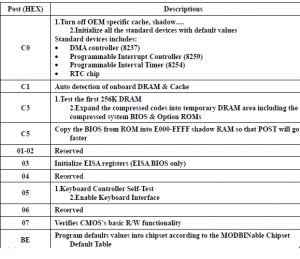
AWARD Bios Code Definition-3
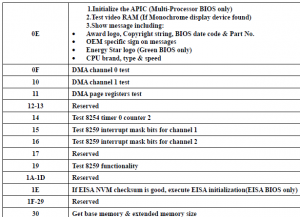
AWARD Bios Code Definition-4
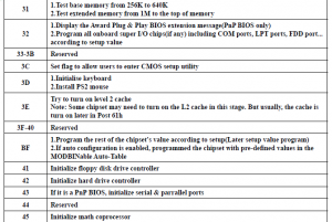
AWARD Bios Code Definition-5
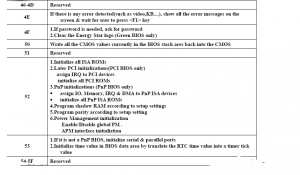
AWARD Bios Code Definition-6
