Essence of Mainboard Power Supply Circuit] Attached with beautiful big picture
To understand the quality and service life of the entire motherboard, judging the quality of the power supply module is one of the best ways. A good power supply module output will not have any voltage fluctuations or clutter, which provides a clean and stable voltage for the CPU and other components. A poor power supply module can cause voltage fluctuations and clutter, and even malfunctions such as computer restarts, crashes, and the infamous blue screen . If the circuit uses poor quality aluminum electrolytic capacitors, they will leak, swell or even explode . It is often a wearing part in the motherboard circuit. And a high-quality power supply module circuit can ensure that you have a stable system, durable.
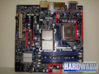
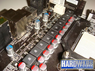
The power supply circuit is easy to identify. Because it is the only motherboard circuit that uses an inductor ( coil ) , the power supply module can usually be found near the inductor. Usually the power supply module surrounds the&nb
sp;CPU ; however, you will find some inductance scattered on the motherboard, usually close to the memory and near the Southbridge chip. Similarly, they provide the required voltage for these components.
1. Recognize the main components of the main components of the
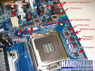
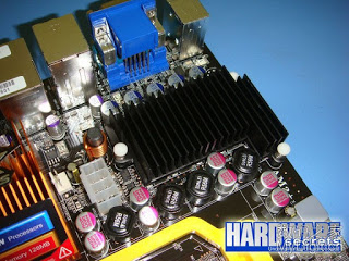
power supply module, as mentioned above, 1 inductance (can be composed of two materials, iron core or ferrite), 2. transistor, 3. capacitor ( good motherboard will provide durability Of aluminum electrolytic capacitors ) . Transistor circuit power supply module called MOSFET ( Metal Oxide Semiconductor Field Effect Transistor ) technology produced , known simply as ” the MOSFET .” Some motherboards use passive cooling – a heat sink to cool the “ MOSFET ”. There is another very important component called ” PWM ” controller, and the same well-designed and small “MOSFET driver”. 
;Next, their function will be explained.
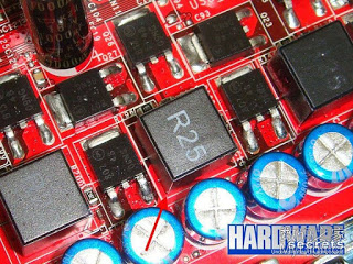
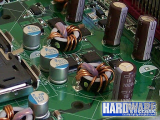
As mentioned earlier, you can find two types of inductors for power supply modules: iron core or ferrite. Compared with iron core inductors, the power loss of ferrite inductors is lower: According to Gigabyte, it is 25% lower ( Gigabyte ’s authority in the motherboard industry can be seen, which will be mentioned later ), lower electromagnetic interference and better resistance Rusty. It is easy to
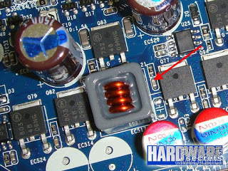
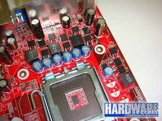
distinguish between the two: the iron core inductor is usually “open”, you can see there is a thick copper coil; and the ferrite inductor is “closed”, usually with a letter R on the top Logo . In Figure 4 and Figure 5 you can compare the differences between them. However, there is an exception to ferrite inductors, which are large, round and “open”, as shown in Figure6. This ferrite choke is easy to identify because its core is horizontal.
There is also a concept in the power supply module called “phase”. Is it a bit confusing, don’t worry, we will explain in detail.
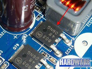
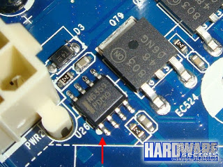
Although all motherboard power supply modules useMOSFETs, there are good and bad. Good MOSFET of the switch resistance is low –this parameter is called “the DPS“, less heat( relative to conventional MOSFET least 16% of the heat, but also said Gigabyte ), a volume smaller than a conventionalMOSFET. There is a simple way to distinguish the two. The traditional MOSFET has three pins . The center pin is usually low-break and floating. The low-impedance MOSFET has four or more pins and are all soldered to the motherboard . You can see the difference betweenFigure7and Figure8.
The power supply module generally has twoMOSFETsper phase. While cheaper motherboards use only one enhancedMOSFET, there are also threeMOSFETsper phase. So the best way to calculate the number of phases is to count the inductance, not the numberMOSFET .
The capacitors used in the power supply module circuit can be divided into traditional electrolyte type capacitors or solid aluminum capacitors. We have shown the differences between them, see Figure 2 . Solid aluminum capacitors are better than ordinary ones because they are less likely to expand or leak . If your motherboard is produced by a regular manufacturer ( alluding to cottage products, foreigners also know ?), You should find their manufacturers. The tradition of Nissan capacitors is to prevent bulging, leakage, and explosion ( three defenses? Little Japan is famous for things ). We have published a detailed explanation on how to identify Nissan capacitors ( there are too many domestic fakes, I ca n’t hold my face … )
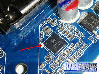
Each voltage output is controlled by an integrated circuit called PWM controller. For example, it is a central processor, memory, chipset, etc. (PWM controller can control two independent voltage outputs ) . If you look around the entire CPU socket, you should be able to find the PWM controller that powers the CPU , see Figure 2 and Figure 9 .
Finally, we have a smaller integrated circuit called MOSFET driver . The power supply module will use a MOSFET to drive each phase, so each driver drives two MOSFETs . Cheap motherboards will replace the driver with additional MOSFETs , so this design of the motherboard has three MOSFETs per phase , not two as usual.
3. Phase
( personally feel that this chapter is more difficult, please skip it if you do n’t have a certain electrical foundation, or see my red letter to mark the part )
The power circuit of the power supply module has several parallel work to provide the same output voltage–especially refers to theCPUVoltage. However, they work at different times, hence the name “phase”. We will explain in detail how it works, so don’t be afraid ( foreigners are cute ). Just like many manufacturers and enthusiasts discuss the number of power supply phases on the motherboard, we hope to extend this topic.
Let’s take theCPUpower supply module as an example. If the circuit has two phases, each phase will operate50%of the time to generate theCPUvoltage. If this same circuit is composed of three phases, each phase will work33.3% of thetime; four phases, each phase will account for25%. There are six phases, and each phase will work16.6%of the time. And so on.
There are several advantages to having more phases in the power module circuit. The most obvious is that theMOSFETload is lower at this time, extending the service life, while reducing the operating temperature of these components. Another benefit is that the normal output voltage of multi-phase is more stable and less turbulent.
Adding more phases requires adding more components, which will increase the cost of the motherboard. Cheap motherboards minimize phase.
Very importantly, when the manufacturer says that the motherboard has six-phase power supply, it refers to theCPUPower supply module.
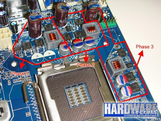
Each voltage phase uses an inductor, two or three MOSFETs , one or more electrolytic capacitors, and a MOSFET driver- this last component in the low-end motherboard can be replaced by a MOSFET . As you can see, the number of components will not stay the same. Currently the only best way to calculate the number of phases is to count the inductance. ( Note that there are exceptions ; we will explain later ) . For example, in Figure 11 (Charts 1 and 2) there are three phases.
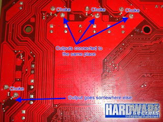
There is one exception. There are some motherboard chipsets and memory power supply inductors located near the CPU . It is not accurate to rely solely on the number of inductors to determine the number of power supply phases. Below : Although it seems to have four phases, it is three-phase, just like the only three phases are used to generate the CPU voltage ; in this motherboard, the fourth phase is used to generate the memory voltage. We want to teach you how to get the accurate phase number in one second.
One of the four inductors on the back of the motherboard should be ignored. In Figure 11, you can see that the inductance in the motherboard’s CPU power supply module is the same pole … Because all the inductances in the same phase produce the same level, only those connected together should be calculated . This can be seen through the copper surface. In Figure 13 we show that the inductors are soldered together. As you can see in Figure 12 , only three inductors are connected together, and the fourth inductor goes to the memory slot.
Figure 13: Correct counting inductance.
The last example is that we want to take you to see the high-end motherboard with 10 phase power supply ( see picture ) . Go MOSET the radiator out fine, we took this picture ( really burn bag ah ).
Now that you know how to correctly identify and count the phase of the power supply module, this time, let’s explain how the power supply module circuit works.
4. How it works The
power supply module circuit gets + 12v voltage from ATX12V EPS12V and converts it to ( central processor, memory, chipset, etc. ) . This conversion is a DC-DC converter , also known as a switching power supply, just like the power supply of a PC . The PWM- pulse width modulation controller is the core of this process. The PWM generates a square wave signal according to the phase. From this signal, it is determined by the load voltage, that is, its duty cycle is proportional to the output target value (for example, 50% duty cycle: then half the time output low potential-usually zero potential, another 50 % Time to output high potential-this is the + 12v of the power supply module .
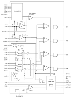
p;to output the correct voltage. Even the smooth completion, and vice versa. The PWM controller (NCP5392) of the CPU power supply module often appears on the circuit diagram of FIG. 15 . You can easily identify the voltage definition pins (VID0 to
Figure 15: PWM controller.
Two MOSFETs and one inductor are used for each phase . PWM cannot provide enough current to switch these MOSFETs , so a MOSFET driver is required for each phase . Usually the MOSFET driver is a small integrated circuit. In order to reduce costs, some manufacturers use a discrete MOSFET for driving on low-end motherboards .
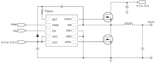
In Figure 16, you can see that the basic diagram of a certain phase (the loop is omitted ) is driven by an NCP5359 MOSFET . EPS12V ATX12V is supplied to MOSFET and MOSFET driver ( marked on it ” 10 V to 13.2 V ” and ” 4v to 15 V) . In this figure you can see two
MOSFETs and inductor and capacitor. This feedback signal and inductance and CS + ( CSP) and CS- (CSN) pin in parallel. This PWMProvide these pins and an enable terminal EN to activate the circuit.
As you can see in Figure 15 , there is a PWM signal output for each phase . It should be explained that a pulse width modulated signal is a square wave whose pulse width (duty cycle) varies depending on the load voltage (this is why this technique is called pulse width modulation ) . Assuming that the output voltage is stable, all pulse width modulated signals will have the same pulse width, that is, each square wave “signal” is the same. However, there is a delay between them. Depends on the alternation of the phase.
For example, in a circuit with only two phases, the two PWM signals will be operated separately. So when the first phase is turned on, the second phase will be turned off, and vice versa. This will ensure that each phase will be 50% of the time. The four phases of the pulse width modulation signal of a circuit will be activated in the same way : the first phase appears first, then the second phase is activated, then the third phase, then the four phases. When one phase is on, all others are off. In this case, each phase will account for 25% .
More phases, less time for each phase. As mentioned earlier, this reduces the heat release of each MOSFET and the life of the component is longer.


