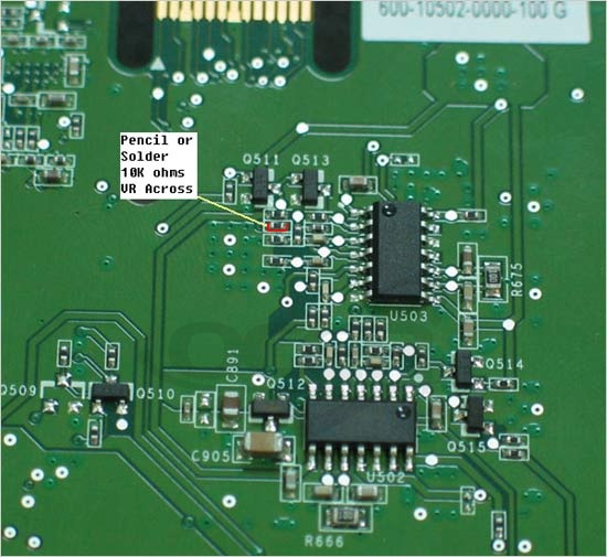
We are talking about from low to high, first Geforce 7 series entry-level model: Geforce 7300GT. It uses the model for the P456 in the public version of the PCB. Marked with red circle in Figure 1 is the core voltage to modify the resistance point. The simplest and most common way is to use a 2B pencil sharpened stick the sheet resistance of conductive graphite can delineate the side line to connect its upper and lower poles, with a short way to increase the power supply voltage in the circuit. Pencil draw a thicker, the lower the resistance of graphite lines to enhance the higher voltage. Users in practice one should not draw the thick, you can try again until overclocked to the appropriate level. If the pencil draw a thick, enhancing the voltage is too large, you can use the eraser in addition to re-start. Finally, adjustment is complete, with the nail polish applied to delineate the protection and curing of graphite lines. Note that the core of the heat will raise the huge increase with voltage, heat can not be sloppy work, the best time in the graphics driver to monitor the core temperature display. If you want to get a higher voltage, you could use more content 4B graphite pencil, or on poles in this resistance, and even a 10K ohm variable resistor VR. If you use a VR resistor, be sure to keep in mind before you make the initial resistance to maximum power, and then gradually reduce the resistance to obtain the required voltage, so that the voltage is too large to prevent the core burning.

Red circle in Figure 2 as a resistance change memory voltage point, the specific modification method with the same core. Also note that when the heat memory, heat sink affixed to the memory particles are simple and effective way.

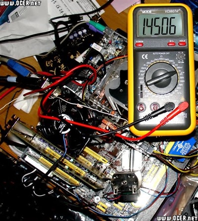
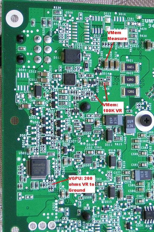
Figure 2 This is a public version of the backside of the PCB Geforce 7600GT, the public version of the 7600GT is still using P456 PCB, so the voltage changes with the Geforce 7300GT is basically the same point. Figure 3 “VGPU Measure” at the core voltage measurement points, “VMem Measure” is the memory voltage measurement points. General approach is to measure contact measurement points with a multimeter red pen, black pen ground, usually caught in the metal plate on the card. By measuring the core in 2D mode when the voltage is 1.3v, 3D mode is 1.36v, and the memory has been around 2v.
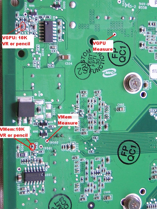

In order to increase GPU voltage, the need for the red circle icon in the upper left corner of the resistance of circuit changes. The resistor 415 in Europe, only a sharpened 2B pencil, you can easily be reduced to 385 resistance in Europe, while the core voltage from 1.36V up to 1.46V. Another way is to connect a 10K ohm rheostat, so you can fine-adjust the voltage. However, welding requires a strong ability, even if you do not accidentally short circuit the consequences are unimaginable power. Again, adjust the rheostat need to pay attention, most began to spin the knob to the maximum resistance at gradually reducing the resistance to enhance the voltage, while monitoring the voltage with a multimeter. Memory voltage regulator basically similar, the red circle on the bottom left of the resistance adjustment on OK. Resistance is the resistance of the original 625 in Europe, almost every reduction of 25 ohm resistor can improve voltage 0.1V. Similarly, you can choose a pencil or a 10K ohm rheostat. Generally speaking, the core voltage was increased to 0.1 ~ 0.2v, memory voltage was increased 0.2 ~ 0.3v is enough. 24 pipeline 7900GT performance has been strong enough, can still be a rice person put it over the pages torn out. This card must be modified when the twelfth to be careful, if defective and that the yuan is equivalent to a thousand dollars an instant dead. This public version of the 7900GT voltage modify the applicability of the program is relatively broader, because the PCB circuit design, manufacturing process more stringent, complex, almost all of the AIC manufacturers and distributors have been in the public version of the design.

Figure 4
VGPU Measure with a multimeter to measure the point-point and memory Vmem Measure the voltage. In 2D and 3D mode, the default core voltage remained at 1.2v, the default memory voltage is has been working in 2.02v. Control the core voltage for the 1K ohm resistor, the left pole in its welding a 50K ohm resistor VR ground, gradually reduce the block can get a higher core voltage. Memory voltage modification is in the red circle in the diagram on the resistance. Its default is 608 ohms resistance, combined with a pencil Scratch and multimeter measurement method reduces it to 553 ohms, the voltage can be increased to 2.23v. Of course you can, and even a 10K ohm resistor VR precise adjustment.
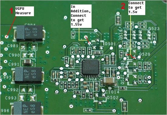
Then I will introduce a more simple way to modify the Geforce 7900GT core voltage. Figure 5
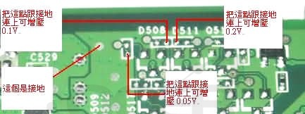
As long as the points marked in Fig ground will be able to get the corresponding boost. Described here is best not to use the pencil line, otherwise too much will affect the impedance of the core power supply stability. Recommended to connect the points with conductive silver paint to get perfect results. In general, under the premise of ensuring the heat, the core pressure to 1.5v is safe. But in order to pressure the insurance we recommend only to 1.45v. When crossed with a conductive silver paint must not connect must pay attention to other conductor, causing a short circuit here is very dangerous.
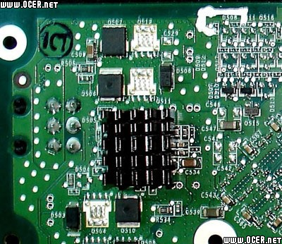
Figure 6

If your hands are conductive silver paint pen, will find it all easy.
The public version of the 7900GS and 7950GT with the 7900GT the same PCB design, not to repeat the description here.
Different PCB makes the voltage transformation with the 7900GT 7900GTX is very different, but 7800GTX 512M version is very similar. Figure 7 with a multimeter red pen contact with the voltage measurement point, black ink ground (contact card bracket) can see that the default core voltage of 1.4v.

Figure 7
Memory voltage is measured using the same method as long as the figure 8 “VMem Measure” point can be. 7900GTX uses 1.1ns GDDR3 memory default voltage of 2.12v. Marked in Figure 8 bottom core voltage control resistor soldered a 200 ohm resistor to ground the VR, the resistance can be improved to reduce the core voltage. Modifying the memory voltage between two points marked with a 100K ohm VR welding resistance can be controlled memory voltage.
Finally to have the card Wong: Geforce 7950GX2. Voltage changes in the way described before the first point: As the 7950GX2 dual-card design to the special aspects of much heat there is, even in the default frequency of its work under the default voltage high heat. Therefore strongly recommended super heat means ready to make this change after work. As GeForce7950GX2 is composed of two PCB, so you need to first carry out this PCB separation after modification. From the left “VGPU Measure” measure of its core remain at the default voltage of 1.3v or so. Shown in Figure 9 connected with conductive silver paint and left the middle of the two points can be 1.5v and 1.55v respectively the core voltage.
If you think 1.55v is not enough, Figure 10 can teach you how to get 1.6v and 1.65v. (Excitement do not forget to observe the temperature)

Core and memory voltage test points, connect them with a multimeter red pen, black pen to ground.

Figure 11
7950GX2 memory default voltage of 1.92v, with a pencil or a VR resistor connected polarization resistance under the icon out of the adjustable voltage of the memory you want.
Geforce 7 graphics full range of public-voltage circuit board modification introduced here on all over. Pressure in the graphics experience the fun of overclocking before those eager to remind the players: For graphics, the circuit transformation is that it does not return. Should improper operation, the graphics card is likely to start the moment you just say goodbye. Even if you arrange everything very properly, it will forever lose the warranty. Please think twice before you ah!