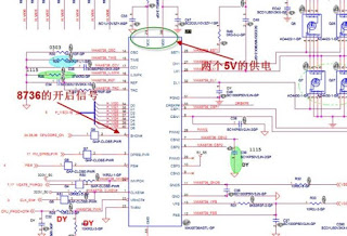
Temporary work, when receiving a client machine repair, COMPAQ’s V3000, Oh, the classic models, this machine is the most frequent failures card air welding, and presumably that we all know, the younger brother would have been prepared for throwing about BGA’s. But nothing better to connect the adjustable power supply looked at, the current went to 0.27, the problem does not appear to graphics, the current is so low. Should not be too CPU, then disassemble. Open the machine and found that this board is 945 set of explicit, plate number Akita. Simple test of the power supply about every major show that I was right, it really is not CPU power, L28 and L26 two inductor PWM waveform is not, then shifted the focus of the maintenance aspects of the Vcore. Akita some of the models of the Vcore circuit is done by the MAX8736 IC PWM control chip Fengyun, measured with an oscilloscope on the G-tube Q6 pole, the moment of power did not wave, that is the PWM circuit did not work, then go to Charles MAX8736 working conditions, first to see 8736 feet of the two power supply pins 21 and 30 feet, both feet has 5V voltage. Supply of electricity is no problem, and then to check 4 pin SHDN # signal, this signal is a 8736 foot-powered open, measuring voltage is only 0.8V, which is obviously wrong, normally the turn signal should be around 3V.
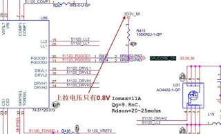
Be easier to find the point of failure, this board should belong to spike, and along the circuit to check CPUCORE_ON, the signal is from the TPS51120 (U35) the IC 30 feet and 11 feet to the issuance, R415 Zheke pull measurement across the resistor, the voltage is only about 0.8V, while the R415 should be a termination voltage of 3.3V, the other end CPUCORE_ON the signal, and now pull the voltage 3D3V_S0 voltage is only 0.8V, resulting in a low power signal CPUCORE_ON level, then continue to investigate 3D3V_S0 the voltage.
Then press the circuit to check, 3D3V_S0 by 3D3V_AUX_S5 the voltage through the U39 tube for the conversion of MOS to measure the U39’s 5678 feet, 3.3V voltage is normal, measuring 4 feet, and found that G voltage is only 0.1V, This is obviously not turn, then together to see the principle of this circuit, the actual figure from the Q15 is used to do a switch, with Q15’s on and off, to provide to the U39 and U38 G pole control voltage . Measurement Q15, S pole is 0.1V voltage, and S pole voltage is DCBATOUT to provide through the R241, R241 measured at both ends, one end is 19V, the other side is 0.1V, the multimeter to the resistance to open files, the amount of R241, 35M ohm resistance actually have, and R241 in the schematic of a 15K resistor is, apparently R241 has been broken, and the amount of R243 a bit this resistance, the resistance is also found around 15M ohms, the resistor is also bad, did not find 15K resistance, only to find a 330K resistor, had come with a 10K resistor for R241, after the installation of two resistors, power on, current up and running smoothly, until 1.2A, should be able to light machine.
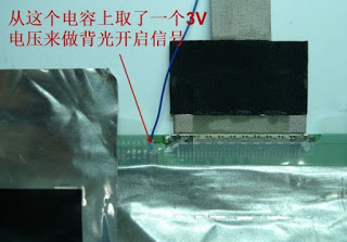
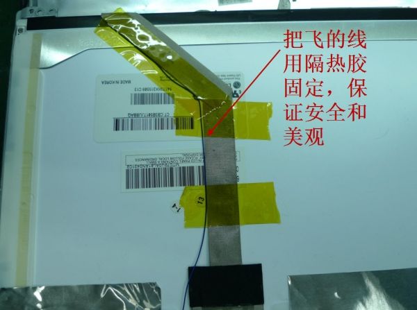
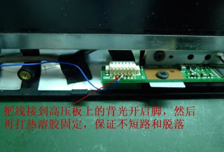
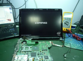
Connected to the screen test machine, that actually does not shine, then a closer look, there COMPAQ’s LOGO, but there is no backlight, and then a bit displays can display properly, it seems that the backlight control signal is not issued to, measuring a little LCD interface 34 feet BLON_OUT, voltage is 0, which signals the opening of the backlight, the normal voltage is 3.3V, this signal is issued by the EC to, but the machine does not have other problems, do not bother to engage in EC, directly From there, fly wire screen to high pressure over the backlight turn on the signal board feet. This process is relatively simple, would not have text descriptions, and Figure it wants to.
After these steps do a good job, re-power on, backlight can be normally open, the machine repaired.


